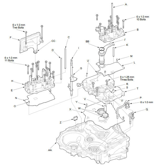
Honda Fit: Valve Body and ATF Strainer Removal (A/T)
-
Remove the ATF feed pipe (A) from the regulator valve body (B).
-
Remove the ATF feed pipes (C) (D) from the servo body (E).
-
Remove the ATF strainer (F) (two bolts).
-
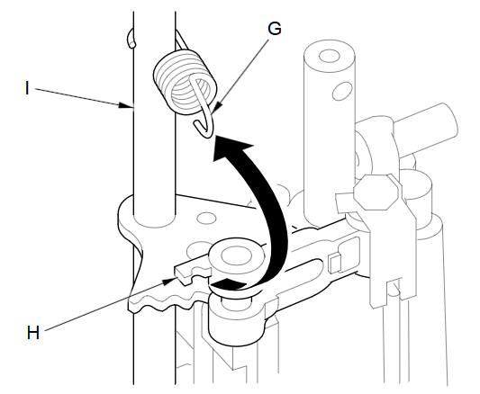
Unhook the detent spring (G) from the detent arm (H), and remove the control shaft (I).
-
Remove the regulator valve body (10 bolts).
-
Remove the stator shaft (J) and stator shaft stop (K), then remove the regulator separator plate (L) and two dowel pins (M).
-
Remove the servo body (11 bolts), then remove the separator plate (N) and two dowel pins (O).
-
Remove the ATF joint pipes (P) (Q).
-
Remove the cooler check valve spring (R) and cooler check valve (S), then remove the main valve body (T) (three bolts). Do not let the check balls (U) fall out.
-
Remove the ATF pump driven gear shaft (V), then remove the ATF pump gears (W).
-
Remove the main separator plate (X) and two dowel pins (Y).
-
Remove the ATF magnet (Z), clean and reinstall it in the torque converter housing (AA).
-
Remove the O-ring (BB) from the stator shaft, and remove the O-ring (CC) from the ATF strainer. Install new ones when installing the valve bodies.
-
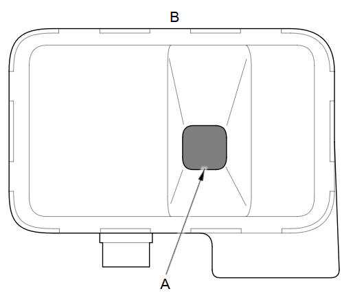
Clean the inlet opening (A) of the ATF strainer (B) thoroughly with compressed air, then check that it is in good condition and that the inlet opening is not clogged.
-
Test the ATF strainer by pouring clean ATF through the inlet opening, and replace it if it is clogged or damaged.
See also:
High-Mount Brake Light Bulb
High-mount brake light bulb is a LED type. Have an authorized Honda dealer
inspect
and replace the light bulb. ...
Viewing the Route
Map Screen
After calculating the route to your
destination, the route is displayed on
the map screen.
As you drive, the system tracks your
position on the map in real time and
provides guida ...
Vehicle Storage
If you need to park your vehicle for an extended period (more than 1 month),
there are several things you should do to prepare it for storage.
Proper preparation helps prevent deterioration and mak ...
Categories
