Honda Fit: Clutch Disassembly (A/T)
Special Tools Required
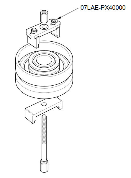
- Clutch Spring Compressor Set 07LAE-PX40000
-
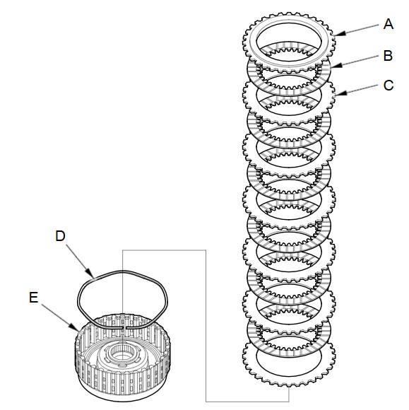
Remove the snap ring with a screwdriver.
-
Remove the clutch end-plate (A), the clutch discs (B) (6), the clutch wave-plates (C) (6), and the wave spring (D) from the 1st clutch drum (E).
-
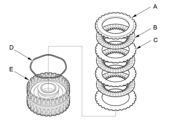
Remove the clutch end-plate (A), the clutch discs (B) (3), the clutch flat-plates (C) (3), and the wave spring (D) from the 2nd clutch drum (E).
-
Remove the clutch end-plate (A), the clutch discs (B) (4), the clutch flat-plates (C) (4), and the wave spring (D) from the 4th clutch drum (E).

-
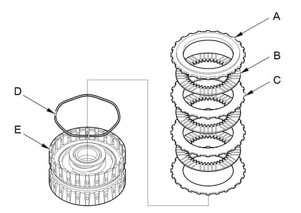
Remove the clutch end-plate (A), the clutch discs (B) (3), the clutch wave-plates (C) (3), and the wave spring (D) from the 4th clutch drum (E).
-
Remove the clutch end-plate (A), the clutch discs (B) (3), the clutch wave-plates (C) (3), and the wave spring (D) from the 5th clutch drum (E).

-
Install the clutch spring compressor set.
-
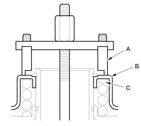
Set the clutch spring compressor attachment (A) on the 1st clutch spring retainer (B) so the clutch spring compressor attachment works on the clutch return spring (C).
-
If either end of the clutch spring compressor attachment is not set over the clutch return spring end, the spring retainer may be tilted and damaged. If the retainer is tilted when compressing the return spring, reset the clutch spring compressor attachment on the retainer at another range.
-
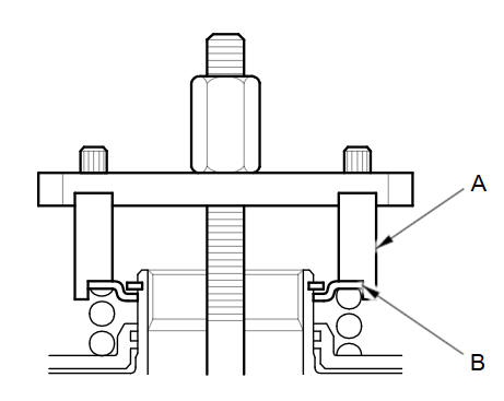
Be sure the clutch spring compressor attachment (A) is adjusted to have full contact with the spring retainer (B) on the 2nd, 3rd, 4th, and 5th clutches, and set either end of the spring compressor attachment over the clutch return spring end.
-
Check the placement of the clutch spring compressor attachment. If either end of the clutch spring compressor attachment is set over an area of the spring retainer that is unsupported by the return spring, the spring retainer may be damaged.
-
Compress the return spring until the snap ring can be removed.
-
Remove the snap ring with snap ring pliers.
-
Remove the clutch spring compressor set.
-
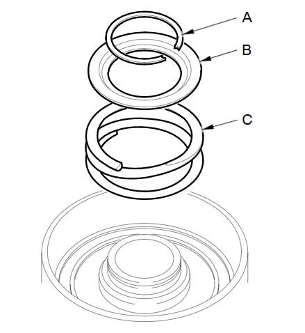
Remove the snap ring (A), the spring retainer (B), and the return spring (C).
-
Wrap a shop rag around the clutch drum, and apply air pressure to the fluid passage to remove the piston. Place a finger tip on the other passage while applying air pressure.
-
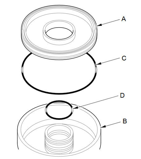
Remove the clutch piston (A) from the clutch drum (B) of the 1st, 2nd, and 4th clutches. Remove the O-ring (C) from the clutch piston, and O-ring (D) from the drum.
-
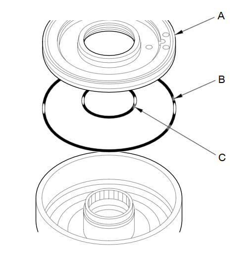
Remove the clutch piston (A) from the clutch drum of the 3rd and 5th clutches, and remove the outer O-ring (B) and inner O-ring (C) from the piston.
See also:
Airbag System Components
The front, front side, and side curtain
airbags are deployed according to the
direction and severity of impact. The airbag
system includes:
1 Two SRS (Supplemental Restraint System)
front airba ...
Rear Door Panel Removal/Installation
Special Tools Required
KTC Trim Tool Set SOJATP2014
Trim Pad Remover Snap-on A 177A or equivalent, commercially available
*Available through the Honda Tool and Equipment Program; call
888-4 ...
Intersection
DEST button
►DEST Menu 2►Intersection
Select the intersection of two streets as the destination. The state or
province for
your current location is displayed at the top of the screen ...
Categories
