Honda Fit: A/T Differential Carrier Bearing Preload Inspection (A/T)
Special Tools Required
- Driver Handle, 15 x 135L 07749-0010000
- Bearing Driver Attachment, 72 x 75 mm 07746-0010600
- Preload Inspection Tool 07HAJ-PK40201
NOTE: If the transmission housing, torque converter housing, differential carrier, tapered roller bearing, bearing outer race, or thrust shim were replaced, the bearing preload must be adjusted.
-
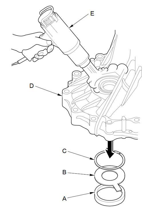
Remove the bearing outer race (A), the 76.2 mm spacer (B), and the 76 mm thrust shim (C) from the transmission housing (D) by heating the housing to about 212 °F (100 °C) with a heat gun (E). Do not heat the housing more than 212 °F (100 °C).
NOTE: Let the transmission housing cool to room temperature before adjusting the bearing preload.
-
Replace the tapered roller bearing when the outer race is to be replaced.
-
Do not use a shim on the torque converter housing side.
-
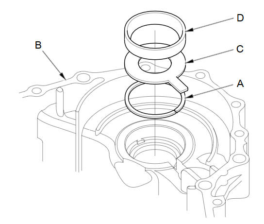
Install the 76 mm thrust shim (A) in the transmission housing (B). If you replace the 76 mm thrust shim with a new one, use the same thickness shim as the old one.
-
Install the 76.2 mm spacer (C) and the bearing outer race (D) in the transmission housing.
-
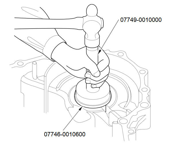
Drive the outer race securely in the housing using the driver handle and the bearing driver attachment (72 x 75 mm), so there is no clearance between the outer race, the spacer, the shim, and the housing.
-
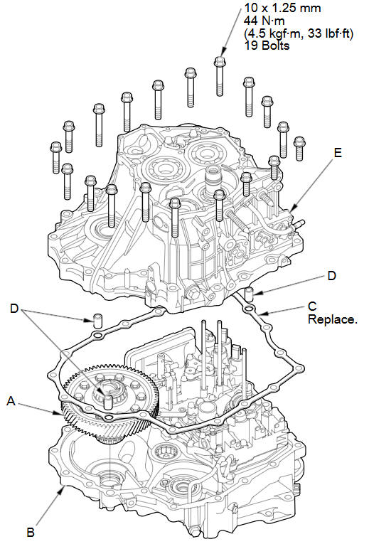
Install the differential assembly (A) in the torque converter housing (B), and install the gasket (C) and the three dowel pins (D) on the housing.
-
Install the transmission housing (E), and install the transmission housing mounting bolts. Tighten the 19 bolts to 44 N·m (4.5 kgf·m, 33 lbf·ft) in at least two steps in a crisscross pattern.
-
Rotate the differential assembly in both directions to seat the bearings.
-
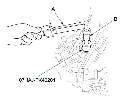
Measure the starting torque of the differential assembly with the special tool, a torque wrench (A), and a socket (B). Measure the staring torque at normal room temperature in both directions.
Standard
New Bearing:
2.7-3.9 N·m
(28-40 kgf·cm, 24-35 lbf·in)Reused Bearing:
2.5-3.6 N·m
(25-37 kgf·cm, 22-32 lbf·in) -
If the starting torque is out of the standard, remove the thrust shim and measure its thickness.
-
Select a new thrust shim. To increase the starting torque, increase thickness of the thrust shim. To decrease the starting torque, decrease the thickness of the thrust shim.
Changing the shim to the next size will increase or decrease the starting torque about 0.5-0.6 N·m (5-6 kgf·cm, 5-5 lbf·in)
THRUST SHIM, 76 mm
No.
Thickness
0A
1.55 mm (0.0610 in)
0B
1.60 mm (0.0630 in)
0C
1.65 mm (0.0650 in)
0D
1.70 mm (0.0669 in)
0E
1.75 mm (0.0689 in)
0F
1.80 mm (0.0709 in)
0G
1.85 mm (0.0728 in)
0H
1.90 mm (0.0748 in)
0I
1.95 mm (0.0768 in)
0J
2.00 mm (0.0787 in)
S
2.05 mm (0.0807 in)
T
2.10 mm (0.0827 in)
U
2.15 mm (0.0846 in)
A
2.20 mm (0.0866 in)
B
2.25 mm (0.0886 in)
C
2.30 mm (0.0906 in)
D
2.35 mm (0.0925 in)
E
2.40 mm (0.0945 in)
F
2.45 mm (0.0965 in)
G
2.50 mm (0.0984 in)
H
2.55 mm (0.1004 in)
I
2.60 mm (0.1024 in)
J
2.65 mm (0.1043 in)
K
2.70 mm (0.1063 in)
L
2.75 mm (0.1083 in)
M
2.80 mm (0.1102 in)
N
2.85 mm (0.1122 in)
O
2.90 mm (0.1142 in)
P
2.95 mm (0.1161 in)
Q
3.00 mm (0.1181 in)
R
3.05 mm (0.1201 in)
A
1.575 mm (0.0620 in)
B
1.626 mm (0.0640 in)
C
1.675 mm (0.0659 in)
D
1.725 mm (0.0679 in)
E
1.775 mm (0.0669 in)
F
1.825 mm (0.0719 in)
G
1.875 mm (0.0738 in)
H
1.925 mm (0.0758 in)
I
1.975 mm (0.0778 in)
(cont'd)
THRUST SHIM, 76 mm (cont'd)
No.
Thickness
J
2.025 mm (0.0797 in)
K
2.075 mm (0.0817 in)
L
2.125 mm (0.0837 in)
M
2.175 mm (0.0856 in)
N
2.225 mm (0.0876 in)
O
2.275 mm (0.0896 in)
P
2.325 mm (0.0915 in)
Q
2.375 mm (0.0935 in)
R
2.425 mm (0.0955 in)
S
2.475 mm (0.0974 in)
T
2.525 mm (0.0994 in)
U
2.575 mm (0.1014 in)
V
2.625 mm (0.1033 in)
W
2.675 mm (0.1053 in)
X
2.725 mm (0.1073 in)
Y
2.775 mm (0.1093 in)
Z
2.825 mm (0.1112 in)
0A
2.875 mm (0.1132 in)
0B
2.925 mm (0.1152 in)
0C
2.975 mm (0.1171 in)
0D
3.025 mm (0.1191 in)
-
Install the new thrust shim, then recheck the staring torque.
See also:
Previous Destinations
DEST button
► Previous Destinations
Select an address from a list of your 50 most recent destinations to use as
the
destination. The list is displayed with the most recent destination at t ...
Torque Converter Housing Mainshaft Bearing and Oil Seal Replacement (A/T)
Special Tools Required
Adjustable Bearing Puller, 25пјЌ40 mm 07736-A01000B
Driver Handle, 15 x 135L 07749-0010000
Bearing Driver Attachment, 62 x 68 mm 07746-0010500
Bearing Driver Attachme ...
Engine Compression Inspection
NOTE: After the inspection, you must reset the ECM/PCM. Otherwise, the
ECM/PCM will continue to stop the injectors from operating.
Allow the engine to reach operating temperature (fan comes o ...
