
Honda Fit: Clutch Wave-Plate Phase Difference Inspection (A/T)
-
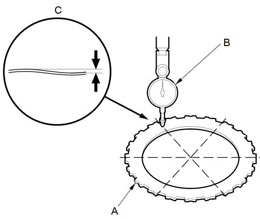
Place the clutch wave-plate (A) on a surface plate, and set a dial indicator (B) on the wave-plate.
-
Find the bottom (C) of a phase difference of the wave-plate, zero the dial indicator, and make a reference mark on the bottom of the wave-plate.
-
Measure the phase differences of 1st clutch wave-plates.
-
Rotate the clutch wave-plate about 5 or 6 tooth while holding the wave-plate by its circumference. The dial indicator should be at the top of a phase difference. Do not rotate the wave-plate while holding its surface, always rotate it by holding its circumference.
-
Read the dial indicator. The dial indicator reads the phase difference of the wave-plate between the bottom and top.
Standard:
0.07пјЌ0.20 mm (0.003пјЌ0.008 in)
-
Rotate the clutch wave-plate about 5 or 6 tooth. The dial indicator should be at the bottom of a phase difference. Zero the dial indicator.
-
Measure the phase difference at the other two tops of the wave-plate by following steps -1 thru -3.
-
-
Measure the phase differences of 3rd and 5th clutch wave-plates.
-
Rotate the clutch wave-plate about 60 degrees while holding the wave-plate by its circumference. The dial indicator should be at the top of a phase difference. Do not rotate the wave-plate while holding its surface, always rotate it by holding its circumference.
-
Read the dial indicator. The dial indicator reads the phase difference of the wave-plate between the bottom and top.
Standard:
0.07пјЌ0.20 mm (0.003пјЌ0.008 in)
-
Rotate the clutch wave-plate another 60 degrees. The dial indicator should be at the bottom of a phase difference. Zero the dial indicator.
-
Measure the phase difference at the other two tops of the wave-plate by following steps -1 thru -3.
-
-
If two of the three measurements are within the standard, the wave-plate is OK. If two of the three measurements are out of the standard, replace the wave-plate.
See also:
Stator Test
Check that there is continuity between each lead (A):
If there is continuity, go to step
24.
If there is no continuity, replace the stator.
...
Audio Menu
AUDIO button (in FM/AM mode)
►AUDIO MENU
Select an item.
The following items are available:
• RDS search: Searches for programs by RDS category.
• Radio Text: Displays the text infor ...
Adjusting the Steering Wheel
The steering wheel height and distance from your body can be adjusted so that
you
can comfortably grip the steering wheel in an appropriate driving posture.
1. Pull the steering wheel adjustment ...
Categories
