Honda Fit: Crankshaft Main Bearing Replacement
Main Bearing Clearance Inspection
-
Remove the bearing cap bridge, the main bearing caps, and main bearing halves.
-
Clean each main journal and main bearing half with a clean shop towel.
-
Place one strip of plastigage across each main journal.
-
Reinstall the main bearings, the main bearing caps, and the bearing cap bridge, then torque the bearing cap bolts to 25 NВ·m (2.5 kgfВ·m, 18 lbfВ·ft) in the proper sequence.
NOTE:
-
Apply new engine oil to the bolt threads and flanges.
-
Do not rotate the crankshaft during inspection.
-
-
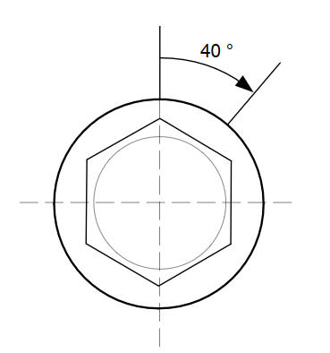
Tighten the bearing cap bolts an additional 40 В°.
-
Remove the bearing cap bridge, the main bearing caps, and the main bearing halves, and measure the widest part of the plastigage.
Main Bearing-to-Journal Oil Clearance
Standard (New):
0.018пјЌ0.036 mm (0.00071пјЌ0.00142 in)
Service Limit:
0.050 mm (0.00197 in)
-
If the plastigage measures too wide or too narrow, remove the crankshaft, and remove the upper half of the main bearing. Install a new, complete main bearing with the same color code, and recheck the clearance. Do not file, shim, or scrape the main bearings or the main bearing caps to adjust clearance.
-
If the plastigage shows the clearance is still incorrect, try the next larger or smaller main bearing (the color listed above or below that one), and check the clearance again. If the proper clearance cannot be obtained by using the appropriate larger or smaller main bearings, replace the crankshaft and start over.
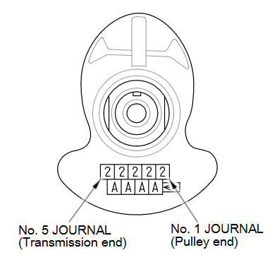
Main Bearing Selection
Block Bore Code Location
Letters have been stamped on the end of the engine block as a code for the size of each of the five main journal bores.
Use them, and the numbers stamped on the crankshaft (codes for main journal size), to choose the correct main bearings. If the codes are indecipherable because of an accumulation of dirt and dust, do not scrub them with a wire brush or scraper. Clean them only with solvent or detergent.
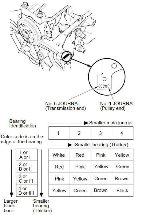
Main Journal Code Location
See also:
Mainshaft Thrust Clearance Adjustment (M/T)
Special Tools Required
Mainshaft Base 07GAJ-PG20130
Collar 07GAJ-PG20120
Mainshaft Holder 07GAJ-PG20110
Remove the 72 mm shim (A) and oil guide plate M from the transmission
housing ...
Steering Angle Sensor Replacement
SRS components are located in this area. Review the
SRS component locations and the
precautions and procedures.
NOTE: Do not damage or drop the combination switch as the steering angle ...
iPod®
...
Categories
