Honda Fit: Special Tools Required
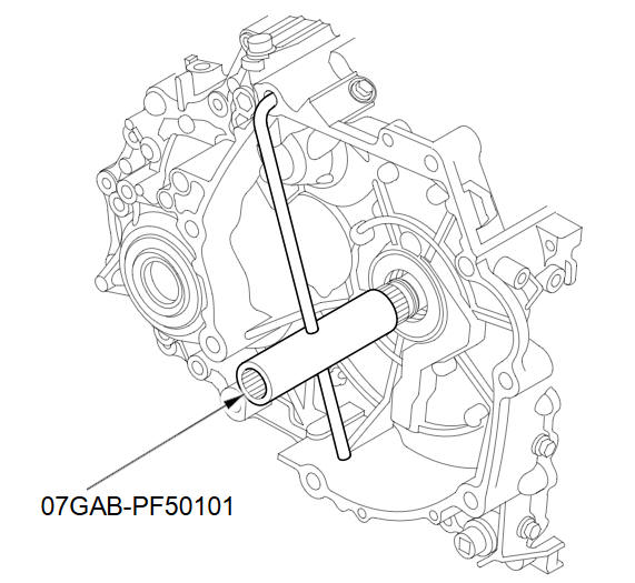
- Mainshaft Holder 07GAB-PF50101
-
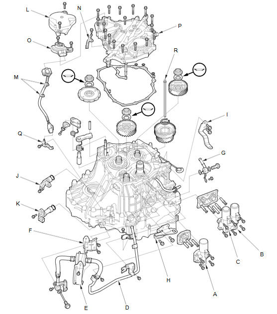
Remove the bolts securing the ATF inlet line (D) and ATF filter holder (E), the line bolt and sealing washers, and remove the ATF inlet line, ATF hose, and ATF filter. Remove the ATF filter bracket (F).

-
Remove the ATF outlet line bolt and sealing washers, the line mounting bolt, and the ATF outlet line (G).
-
Remove the transmission hanger (H) and the breather hose clamp bracket (I).
-
Remove the A/T clutch pressure control solenoid valve A, the ATF joint pipes, the O-rings, the ATF pipe, and the gasket.
-
Remove the A/T clutch pressure control solenoid valve B and C, the O-rings, the ATF pipe, the ATF joint pipes, and the gasket.
-
Remove the input shaft (mainshaft) speed sensor (J) and the output shaft (countershaft) speed sensor (K).
-
Remove the transmission range switch cover (L).
-
Remove the transmission range switch harness clamps (M) from the clamp bracket (N), then remove the transmission range switch (O).
-
Remove the clamp bracket from the end cover (P).
-
Remove the connector bracket (Q) from the transmission housing.
-
Remove the end cover, the dowel pins, the O-rings, and the end cover gasket.
-
Remove the ATF lubrication pipe (R) from the idler gear shaft.
-
Slip the mainshaft holder onto the mainshaft.

-
Engage the park pawl with the park gear.
-
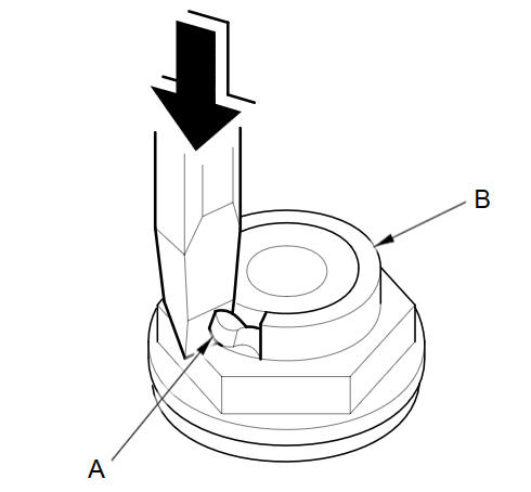
Using a chisel, cut the lock tab (A) off the each shaft locknut (B). Then remove the locknuts and conical spring washers from each shaft.
NOTE:
-
Countershaft and secondary shaft locknuts have left-hand threads.
-
Keep all of the chiseled particles out of the transmission.
-
Clean the old locknuts; they are used to install the press fit idler gears and park gear.

-
-
Remove the snap ring securing the idler gear to the idler gear shaft.
-
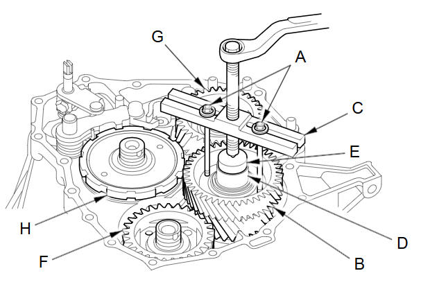
Install 6 x 1.0 mm bolts (A) on the idler gear shaft idler gear (B). Set a puller (C) on the idler gear shaft (D) with a spacer (E) between the puller and idler gear shaft, then remove idler gear shaft idler gear.

-
Set the puller, the 6 x 1.0 mm bolts, and the spacer on the secondary shaft idler gear (F), and remove the secondary shaft idler gear from the secondary shaft in the same manner as the removal of the idler gear shaft idler gear.
-
Set the puller, the 6 x 1.0 mm bolts, and the spacer on the mainshaft idler gear (G), and remove the mainshaft idler gear from the mainshaft in the same manner as the removal of the idler gear shaft idler gear.
-
Set the puller, the 6 x 1.0 mm bolts, and the spacer on the park gear (H), and remove the park gear from the countershaft in the same manner as the removal of the idler gear shaft idler gear.
-
Remove the park pawl, the park pawl spring, the park pawl shaft, and the stop shaft.
-
Remove the park lever from the selector control shaft.
See also:
Using HFL
HFL Buttons
( HFL Talk) button: Press
to go directly to give a command or to answer an
incoming call.
(HFL Back) button: Press to
end a call or to cancel a command.
Help Features
• To h ...
Front Passenger's Airbag Replacement (Removal)
NOTE:
If replacing the front passenger's airbag after deployment,
refer to Component Replacement/Inspection After Deployment
for a complete list of other parts that must also be r ...
Introduction
Congratulations! Your selection of a 2008 Honda Fit was a wise investment.
It will give you years of driving pleasure.
One of the best ways to enhance the enjoyment of your new vehicle is to read
...
