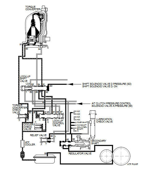
Honda Fit: A/T System Description - Lock-Up System (A/T)
The lock-up mechanism of the torque converter clutch operates in all five gears in D, in 3rd gear in D3, and 3rd and 4th gears in S with the automatic shift mode. The pressurized fluid is drained from the back of the torque converter through a fluid passage, causing the torque converter clutch piston to be held against the torque converter cover. As this takes place, the mainshaft rotates at the same speed as the engine crankshaft. Together with the hydraulic control, the PCM optimizes the timing and degree of lock-up. When shift solenoid valve D is turned ON by the PCM, shift solenoid valve D pressure switches the lock-up shift valve lock-up ON and OFF. A/T clutch pressure control solenoid valve A and the lock-up control valve control the amount of lock-up.
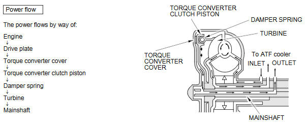
Torque Converter Clutch Lock-up ON (Engaging Torque Converter Clutch)
Fluid in the chamber between the torque converter cover and the torque converter clutch piston is drained off, and fluid entering from the chamber between the pump and stator exerts pressure through the torque converter clutch piston against the torque converter cover. The torque converter clutch piston engages with the torque converter cover; the torque converter clutch lock-up is ON, and the mainshaft rotates at the same speed as the engine.
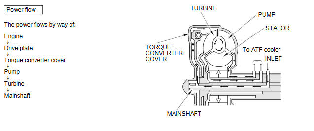
Torque Converter Clutch Lock-up OFF (Disengaging Torque Converter Clutch)
Fluid entered from the chamber between the torque converter cover and the torque converter clutch piston passes through the torque converter and goes out from the chambers between the turbine and the stator, and between the pump and the stator. As a result, the torque converter clutch piston moves away from the torque converter cover, and the torque converter clutch lock-up is released; torque converter clutch lock-up is OFF.
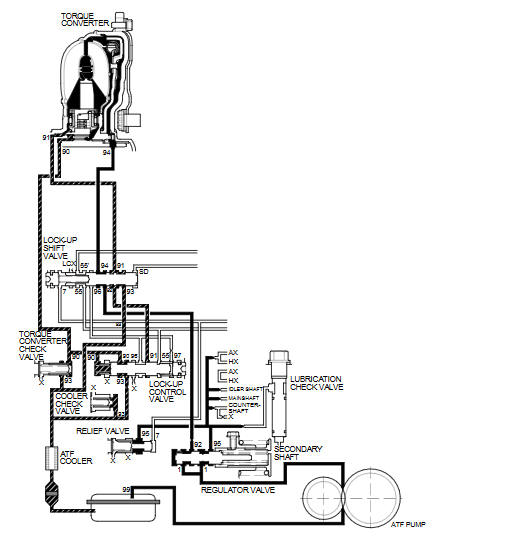
No Lock-up
The PCM commands shift solenoid valve D to remain OFF, and shift solenoid valve D covers the shift solenoid valve D pressure port (SD) to the lock-up shift valve. The lock-up shift valve is in the right side, and uncovers the torque converter pressure port leading to the back of the torque converter. Torque converter pressure (92), regulated by the regulator valve, flows to the lock-up shift valve and becomes torque converter pressure (94). Torque converter pressure (94) enters into the back of the torque converter, and discharges into the circuit from the front of the torque converter. Torque converter pressure enters into the back of the torque converter and is discharged from the front side; this disengages the torque converter clutch piston and the torque converter cover. Under this condition, the torque converter clutch is not engaged; this is the non lock-up condition.
NOTE: When used, left'' or right'' indicates direction on the hydraulic circuit.
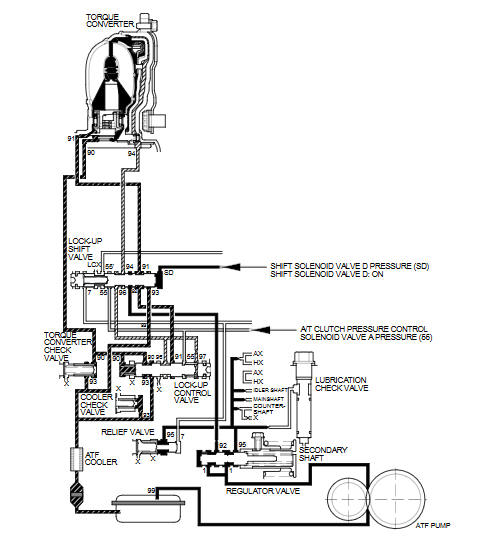
Partial Lock-up
As the speed of the vehicle reaches the programmed value, the PCM turns shift solenoid valve D ON. Shift solenoid valve D pressure (SD) is applied to the right end of the lock-up shift valve to switch the torque converter pressure port leading to the front of the torque converter. Torque converter pressure (91) enters into the front of the torque converter to engage the torque converter clutch piston. The PCM also controls A/T clutch pressure control solenoid valve A to regulate A/T clutch pressure control solenoid valve A pressure (55), and A/T clutch pressure control solenoid valve A pressure (55) is applied to the lock-up control valve. Torque converter pressure (94) drained from the back of the torque converter is applied to the right side of the lock-up control valve, and torque converter pressure (90) is applied to the left side of the lock-up control valve. The lock-up control valve controls the amount of the lock-up by receiving these pressures. The torque converter clutch is engaged partially when torque converter pressure (90) in the left side of the lock-up control valve is higher, and the torque converter clutch is engaged securely according to the amount of pressure in the right side of the lock-up control valve. Under this condition, the torque converter clutch is engaged by pressure entering into the front side of the torque converter; this condition is partial lock-up.
NOTE: When used, left'' or right'' indicates direction on the hydraulic circuit.
Full Lock-up
When the vehicle speed further increases, the PCM controls A/T clutch pressure control solenoid valve A to increase A/T clutch pressure control solenoid valve A pressure (55). A/T clutch pressure control solenoid valve A pressure (55) is applied to the lock-up control valve, and the lock-up control valve is moved to the left side to release torque converter back pressure (94). Torque converter pressure (91) enters into the front of the torque converter, and the torque converter clutch piston is securely engaged with the torque converter cover by torque converter pressure. Under this condition, torque converter back pressure is released fully, causing the torque converter clutch to be fully engaged; this condition is full lock-up.
NOTE: When used, left'' or right'' indicates direction on the hydraulic circuit.
See also:
If the Low Tire Pressure Indicator Comes On
U.S. models
■ Reasons for the indicator to come on
A tire pressure is significantly low. If the compact spare tire* is installed,
the indicator stays on for a while, and then goes off.
& ...
Servo Body Disassembly, Inspection, and Reassembly (A/T)
Clean all parts thoroughly in solvent, and dry them with compressed air.
Blow out all passages.
Inspect the servo body for scoring and damage.
Check all valves for fre ...
Disc Player Error Messages
The chart on the right explains the error messages you may see in the display
while playing a disc.
If you see an error message in the display while playing a disc, press the eject
button. After ...
Categories
