
Honda Fit: Intermediate Shaft Reassembly (A/T)
Exploded View
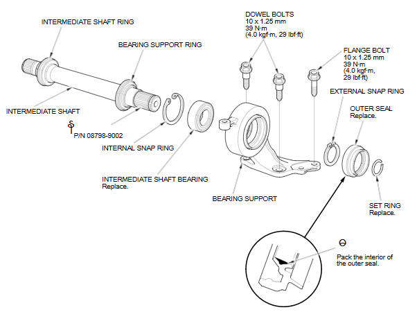
Special Tools Required
- Oil Seal Driver, 65 mm 07JAD-PL90100
- Bearing Driver Attachment, 52 x 55 mm 07746-0010400
- Bearing Driver Attachment, 35 mm I.D. 07746-0030400
- Driver Handle, 15 x 135L 07749-0010000
NOTE: Refer to the Exploded View, as needed, during this procedure.
-
Clean the disassembled parts with solvent, and dry them with compressed air.
NOTE: Do not wash the rubber parts with solvent.
-
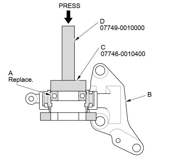
Press a new intermediate shaft bearing (A) into the bearing support (B) using the 52 x 55 mm bearing driver attachment (C), the 15 x 135L driver handle (D), and a press.
-
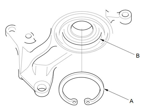
Install the internal snap ring (A) into the groove (B) of the bearing support.
-
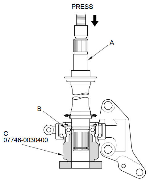
Press the intermediate shaft (A) into the shaft bearing (B) using the 35 mm inner bearing driver attachment (C) and a press.
-
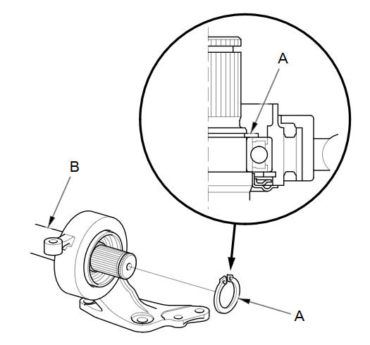
Install the external snap ring (A) in the groove of the intermediate shaft (B).
-
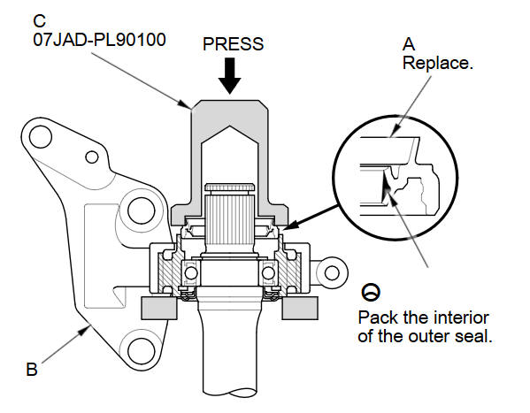
Install a new outer seal (A) into the bearing support (B) using the 65 mm oil seal driver (C) and a press. Press the seal until it is 0В±0.2 mm (0В±0.008 in) below the surface of the bearing support end.
See also:
Transmission Mount Bracket Replacement
Do the battery removal procedure.
Remove the air cleaner.
M/T model: Remove the battery cables (A) from the battery terminal fuse
box.
M/T mode ...
Showing Icons on the Map
MAP MENU (on map)
►Show icon on Map
The icon bar along the bottom of the screen allows you to select the icons
that are
displayed on the map.
Select an icon in the icon bar.
► Se ...
Main Valve Body Disassembly, Inspection, and Reassembly (A/T)
Clean all parts thoroughly in solvent, and dry them with compressed air.
Blow out all passages.
Do not use a magnet to remove the check balls, it may magnetize the check
balls. ...
Categories
