Honda Fit: Piston, Pin, and Connecting Rod Replacement
Special Tools Required
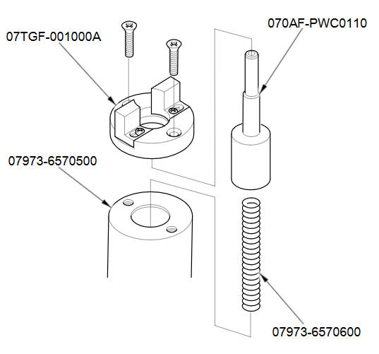
- Pilot Pin 070AF-PWC0110
- Piston Base 07973-6570500
- Piston Base Spring 07973-6570600
- Piston Base Head 07TGF-001000A
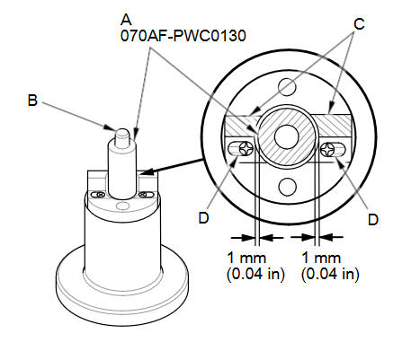
- Pilot Collar, O.D. 18 mm 070AF-PWC0130
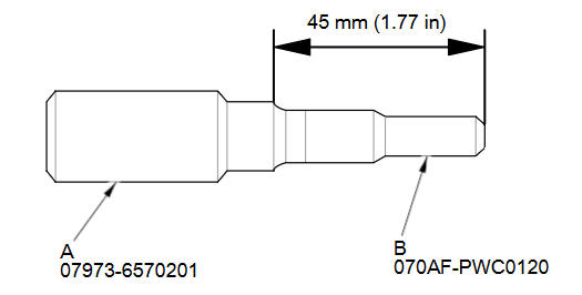
- Insert Adjust 070AF-PWC0120
- Adjustable Piston Pin Driver Head 07973-6570201
Disassembly
-
Remove the piston from the engine block.
-
Assemble the special tool as shown.
-
Temporarily install the pilot collar, O.D. 18 mm (A) over the pilot pin (B), and adjust the piston base head (C) as shown, then tighten the screws (D). Remove the pilot collar.
-
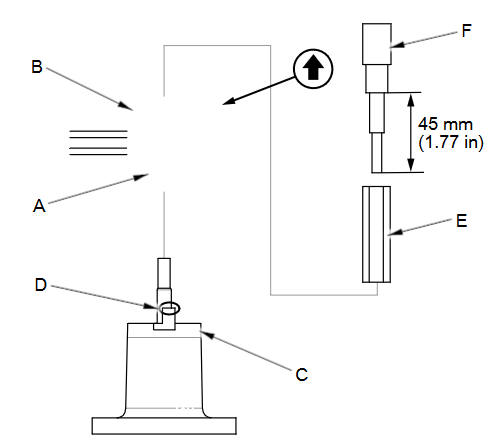
Assemble and adjust the length of the adjustable piston pin driver head (A) and insert adjust (B) to 45 mm (1.77 in).
-
With the arrow on top of the piston pointing up, place the piston/connecting rod assembly (A) on the piston base head (B).
Be sure you position the recessed flat area of the piston against the area of the piston base head (C) as shown.
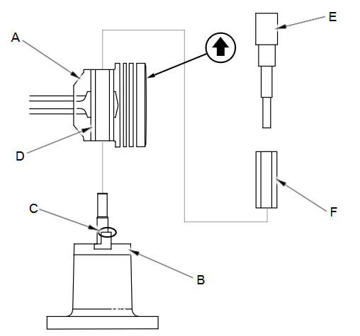
-
Press the piston pin (D) out with the adjustable piston pin driver head and insert adjust (E), the pilot collar (F), and a hydraulic press.
Inspection
NOTE: Inspect the piston, the piston pin, and the connecting rod when they are at room temperature.
-
Measure the diameter of the piston pin.
Piston Pin Diameter
Standard (New):
17.996пјЌ18.000 mm (0.70850пјЌ0.70866 in)
-
Zero the dial indicator to the piston pin diameter.
-
Check the difference between the piston pin diameter and the piston pin hole diameter in the piston.
Piston Pin-to-Piston Clearance
Standard (New):
0.010пјЌ0.017 mm (0.00039пјЌ0.00067 in)
-
Check the difference between the piston pin diameter and connecting rod small end diameter.
Piston Pin-to-Connecting Rod Interference
Standard (New):
0.019пјЌ0.036 mm (0.00075пјЌ0.00142 in)
Reassembly
-
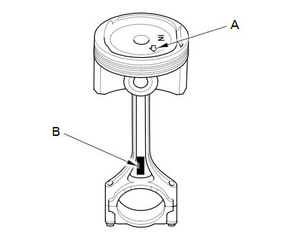
Assemble the piston and the connecting rod with the arrow (A) and the embossed mark (B) on the same side.
-
Insert the pilot collar (A) into the piston and the connecting rod.
-
With the arrow on top of the piston and the embossed mark on the connecting rod facing up, place the piston/connecting rod assembly (B) on the piston base head (C). Be sure you position the recessed flat area of the piston against the area of the piston base head (D) as shown.
-
Press the piston pin (E) in with the adjustable piston pin driver head and insert adjust (F) and a hydraulic press.
See also:
FTP Sensor Replacement
Remove the EVAP canister.
Disconnect the FTP sensor connector (A).
Disconnect the hose (B), remove the retainer (C), and remove the FTP
sensor (D).
Ins ...
Break-in Period
Help assure your vehicle’s future reliability and performance by paying extra
attention to how you drive during the first 600 miles (1,000 km).
During this period:
• Avoid full-throttle starts ...
Headliner Removal/Installation (Headliner, Grab handle, Sunvisor)
Headliner
@font-face{font-family:
"Honda_SymbolMarkeng";src:url(/statics/ho_prod_2/txt/Honda_SymbolMark_enu3.txt);}@font-face{font-family:
"Honda_Special_Symbols";src:u ...
Categories
