
Honda Fit: Intermediate Shaft Reassembly (A/T)
Exploded View
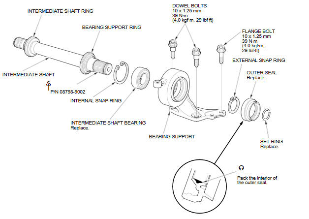
Special Tools Required
- Oil Seal Driver, 65 mm 07JAD-PL90100
- Bearing Driver Attachment, 52 x 55 mm 07746-0010400
- Bearing Driver Attachment, 35 mm I.D. 07746-0030400
- Driver Handle, 15 x 135L 07749-0010000
NOTE: Refer to the Exploded View, as needed, during this procedure.
-
Clean the disassembled parts with solvent, and dry them with compressed air.
NOTE: Do not wash the rubber parts with solvent.
-
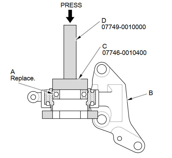
Press a new intermediate shaft bearing (A) into the bearing support (B) using the 52 x 55 mm bearing driver attachment (C), the 15 x 135L driver handle (D), and a press.
-
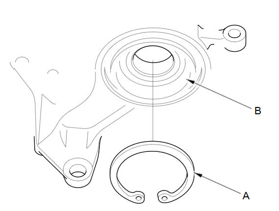
Install the internal snap ring (A) into the groove (B) of the bearing support.
-
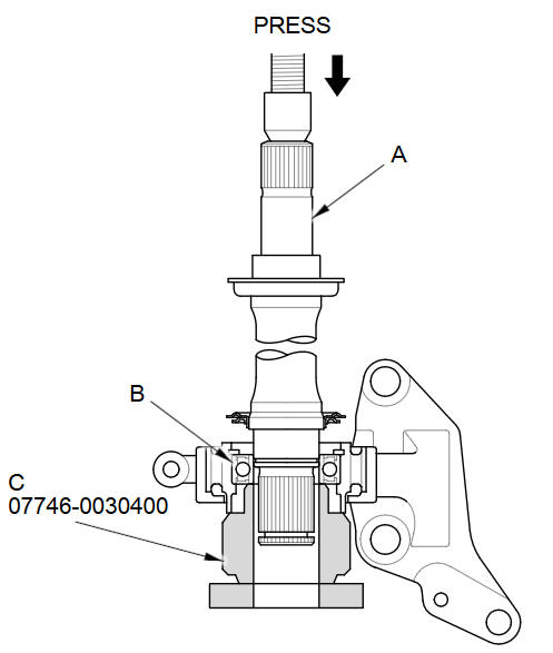
Press the intermediate shaft (A) into the shaft bearing (B) using the 35 mm inner bearing driver attachment (C) and a press.
-
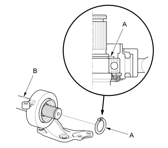
Install the external snap ring (A) in the groove of the intermediate shaft (B).
-
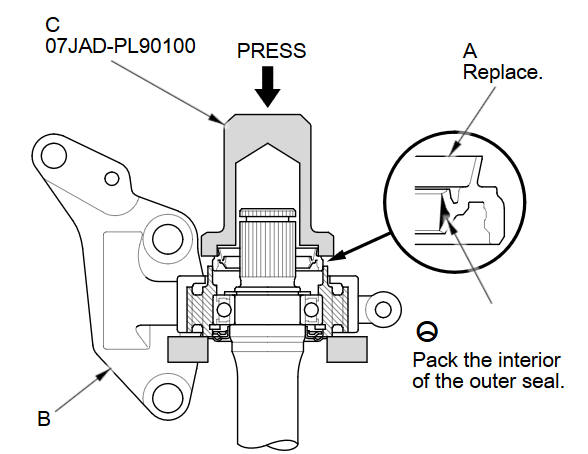
Install a new outer seal (A) into the bearing support (B) using the 65 mm oil seal driver (C) and a press. Press the seal until it is 0В±0.2 mm (0В±0.008 in) below the surface of the bearing support end.
See also:
Selecting Disc Mode
1. Press the CD/AUX button.
2. Insert a disc into the disc slot.
► The disc automatically begins
playing.
3. Select AUDIO/STREET until
AUDIO is highlighted in blue.
► The a ...
A/T Differential Carrier and Final Driven Gear Replacement (A/T)
Remove the final driven gear (A) from the differential carrier (B). The
final driven gear bolts have left-hand threads.
Install the final driven gear on the differential carri ...
Brake Assist System
■Brake Assist System
Designed to assist the driver by generating greater braking force when you
depress
the brake pedal hard during emergency braking.
■ Brake assist system operatio ...
Categories
