Honda Fit: Servo Body Disassembly, Inspection, and Reassembly (A/T)
-
Clean all parts thoroughly in solvent, and dry them with compressed air. Blow out all passages.
-
Inspect the servo body for scoring and damage.
-
Check all valves for free movement. If any fail to slide freely, refer to valve body repair.
-
Coat all parts with ATF during assembly.
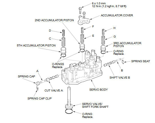
VALVE SPRINGS SPECIFICATIONS
|
Valve Springs |
Standard (New)-Unit: mm (in) |
||||
|
Wire Diameter |
O.D. |
Free Length |
No. of Coils |
||
|
A |
Cut valve A spring |
0.9 (0.035) |
9.9 (0.390) |
22.3 (0.878) |
6.9 |
|
B |
Shift valve B spring |
0.8 (0.031) |
7.1 (0.280) |
23.7 (0.933) |
9.7 |
|
C |
5th accumulator spring A |
2.5 (0.098) |
16.6 (0.654) |
46.9 (1.846) |
7.8 |
|
D |
5th accumulator spring B |
1.9 (0.075) |
10.0 (0.394) |
38.5 (1.516) |
10.6 |
|
E |
2nd accumulator spring A |
1.8 (0.071) |
14.6 (0.575) |
43.8 (1.724) |
7.9 |
|
F |
2nd accumulator spring B |
1.85 (0.073) |
9.4 (0.370) |
32.5 (1.280) |
8.7 |
|
G |
3rd accumulator spring A |
1.8 (0.071) |
14.6 (0.575) |
43.8 (1.724) |
7.9 |
|
H |
3rd accumulator spring B |
1.85 (0.073) |
9.4 (0.370) |
32.5 (1.280) |
8.7 |
See also:
Carrying Cargo
Your vehicle has several convenient storage areas:
• Glove box
• Front door pockets
• Seat-back pocket
• Center pocket
• Cargo area side pocket
• Cargo area, including the rear sea ...
Engine Oil Filter Feed Pipe Replacement
Remove the filter.
Remove the oil filter feed pipe.
Install two 20 x 1.5 mm nuts (A) onto the new oil filter feed pipe, and
hold one nut with a wrench, then ti ...
Reverse Shift Fork Clearance Inspection (M/T)
Measure the clearance between the reverse idler gear (A) and the reverse
shift fork (B) with a feeler gauge (C). If the clearance is more than the
service limit, go to step 2.
...
Categories
