Honda Fit: Intake Manifold/Chamber Assembly Removal and Installation
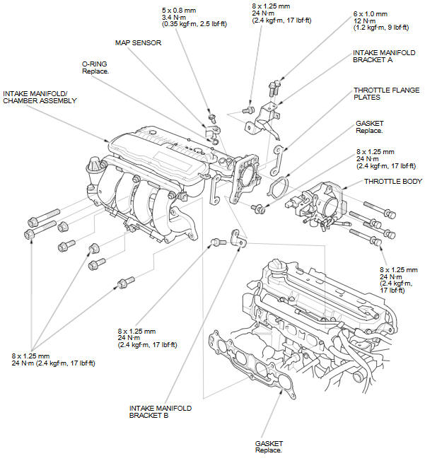
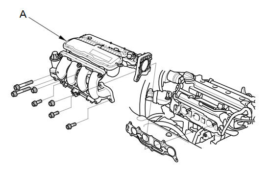
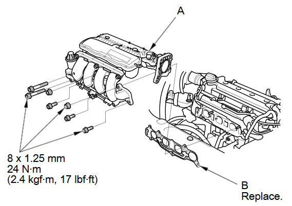
Exploded View
Removal
-
Remove the under-cowl panel.
-
Remove the air cleaner.
-
Disconnect the engine wire harness connectors, and remove the wire harness clamps from the intake manifold chamber:
-
Throttle actuator connector
-
MAP sensor connector
-
EGR valve connector
-
-
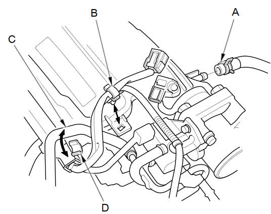
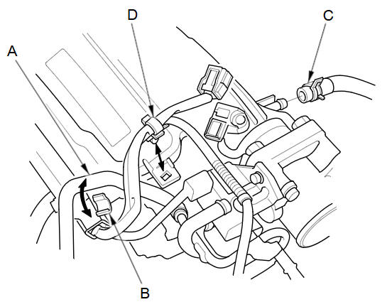
Disconnect the brake booster vacuum hose (A) and remove the harness clamp (B).
-
Remove the water bypass hose (C) from the clamp (D).
-
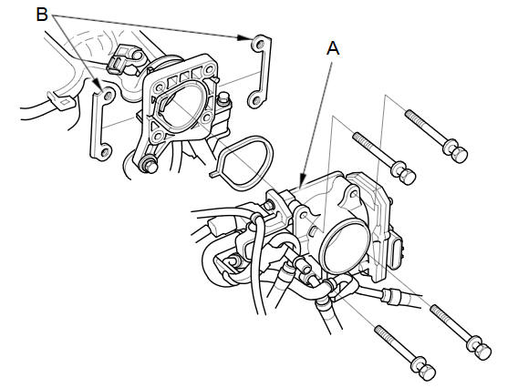
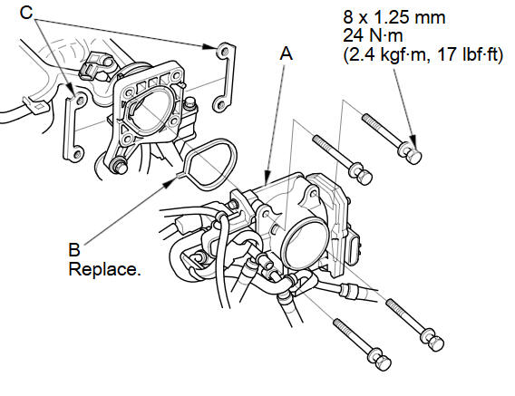
Remove the throttle body (A) without disconnecting the water bypass hoses.
-
Remove the throttle flange plates (B).
-
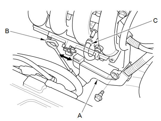
Remove the harness holder (A) and the dipstick (B).
-
Disconnect the PCV hose (C).
-
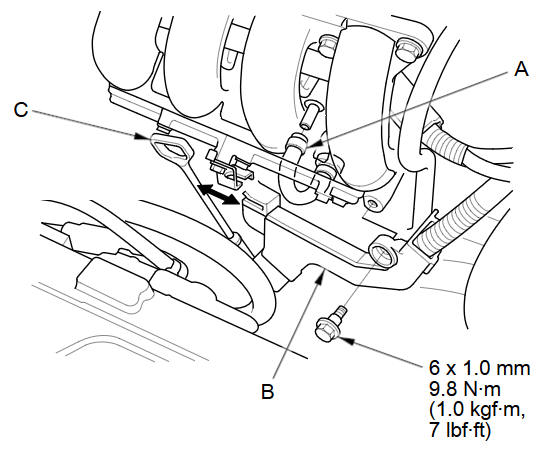
Remove the intake manifold bracket mounting bolts.
-
Remove the intake manifold/chamber assembly (A) from the cylinder head.
-
Disassemble the intake manifold/chamber assembly.
NOTE: Refer to the Exploded View if needed during this procedure.
Installation
-
Reassemble the intake manifold/chamber assembly.
NOTE: Refer to the Exploded View if needed during this procedure.
-
Install the intake manifold/chamber assembly (A) with a new gasket (B).
NOTE: Tighten the bolts and nuts in a crisscross pattern in three steps, beginning with the inner bolt.
-
Loosen the intake manifold bracket mounting bolts (A, B), then loosely install the intake manifold bracket mounting bolts (C, D).
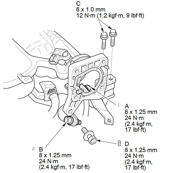
-
Tighten the intake manifold bracket mounting bolts in the numbered sequence shown.
-
Install the throttle body (A) with a new gasket (B), and the throttle flange plates (C).
-
Connect the PCV hose (A).
-
Install the harness holder (B) and the dipstick (C).
-
Install the water bypass hose (A) to the clamp (B).
-
Connect the brake booster vacuum hose (C) and install the harness clamp (D).
-
Connect the engine wire harness connectors, and install the wire harness clamps to the intake manifold chamber:
-
Throttle actuator connector
-
MAP sensor connector
-
EGR valve connector
-
-
Install the air cleaner.
-
Install the under-cowl panel.
See also:
Warm Up TWC Removal/Installation
NOTE: If the warm up TWC is damaged internally, inspect the under-floor TWC
for debris.
Raise the vehicle on a lift.
Remove the bolts (A).
Lower the vehicle.
...
Wheel Bearing Replacement
Separate the hub (A) from the knuckle (B) using the hub dis/assembly tool
and a hydraulic press. Hold the knuckle with the attachment (C) of the
hydraulic press or equivalent tool. Be care ...
Resetting the Clock Settings
INFO button
► Setup ►Other
►Clock Adjustment►Clock Adjustment
Reset all clock settings to the factory defaults.
Select OK under Reset. ...
Categories
