
Honda Fit: Piston Installation
If the Crankshaft is Already Installed
-
Set the crankshaft to bottom dead center (BDC) for each cylinder as its piston is installed.
-
Remove the connecting rod caps, and check that the connecting rod bearing is securely in place.
-
Apply new engine oil to the piston, inside of the ring compressor, and the cylinder bore, then attach the ring compressor to the piston/connecting rod assembly.
-
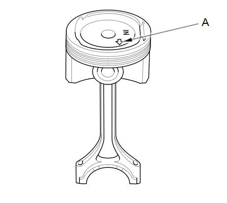
Position the piston/connecting rod assembly with the arrow (A) facing the cam chain side of the engine block.
-
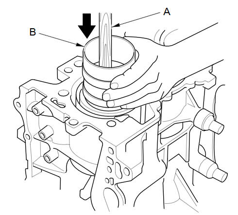
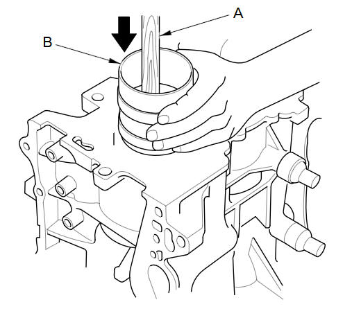
Position the piston/connecting rod assembly in the cylinder, and tap it in using the wooden handle of a hammer (A).
Maintain downward force on the ring compressor (B) to prevent the rings from expanding before entering the cylinder bore.
-
Stop after the ring compressor pops free, and check the connecting rod-to-connecting rod journal alignment before pushing the piston into place.
-
Check the connecting rod bearing clearance with a plastigage.
-
Inspect the connecting rod bolts.
-
Apply new engine oil to the bolt threads and flanges, then install the connecting rod caps with connecting rod bearings. Torque the bolts to 9.8 NВ·m (1.0 kgfВ·m, 7 lbfВ·ft).
-
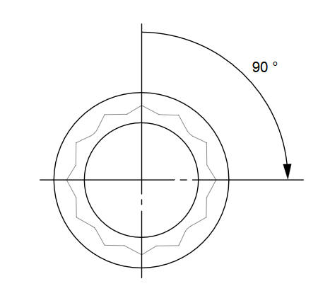
Tighten the connecting rod bolts an additional 90 В°.
NOTE: Remove the connecting rod bolt if you tightened it beyond the specified angle, and go back to step 8 of the procedure. Do not loosen it back to the specified angle.
If the Crankshaft is Not Installed
-
Remove the connecting rod caps, and check that the connecting rod bearing is securely in place.
-
Apply new engine oil to the piston, inside of the ring compressor, and the cylinder bore, then attach the ring compressor to the piston/connecting rod assembly.
-
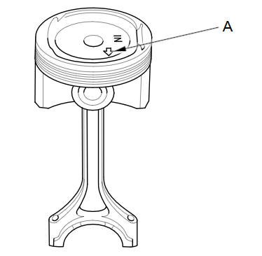
Position the piston/connecting rod assembly with the arrow (A) facing the cam chain side of the engine block.
-
Position the piston/connecting rod assembly in the cylinder, and tap it in using the wooden handle of a hammer (A).
Maintain downward force on the ring compressor (B) to prevent the rings from expanding before entering the cylinder bore.
-
Position all pistons at top dead center (TDC).
See also:
Tailgate Lock Cylinder Replacement
For Some Models
NOTE: Put on gloves to protect your hands.
Remove the tailgate lower trim panal.
Disconnect the tailgate cylinder rod (A).
NOTE: Check for damaged or stress-wh ...
Maintenance MinderTM
If the engine oil life is less than 15%, you will see the Maintenance Minder
messages
appear on the information display every time you turn the ignition switch to ON
.
The messages notify you w ...
Categories
