Honda Fit: Mainshaft Reassembly (M/T)
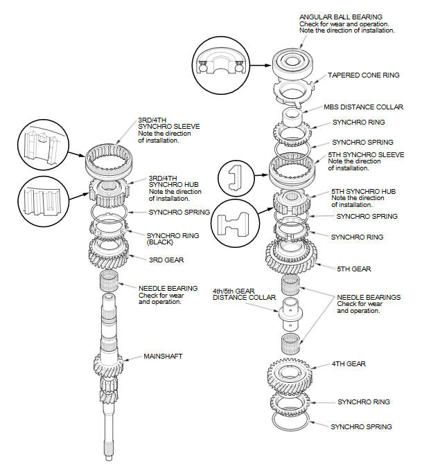
Exploded View
Special Tools Required
- Driver Handle, 40 mm I.D. 07746-0030100
- Bearing Driver Attachment, 30 mm I.D. 07746-0030300
NOTE: Refer to the Exploded Viewas neededduring this procedure.
-
Clean all the parts in solvent, dry them, and apply MTF to all contact surfaces.
-
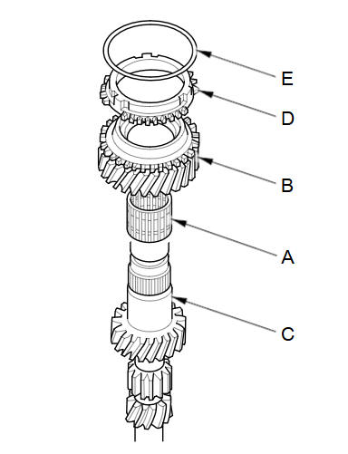
Install the needle bearing (A) and 3rd gear (B) onto the mainshaft (C).
-
Install the synchro ring (D) with the synchro spring (E) onto 3rd gear.
-
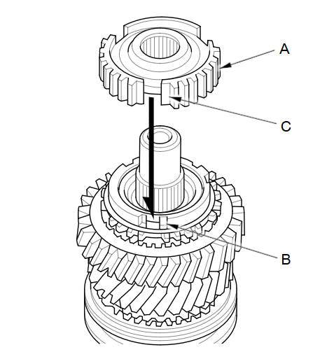
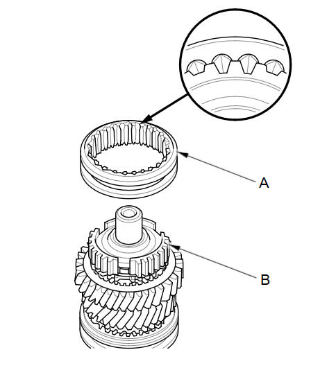
Install the 3rd/4th synchro hub (A) by aligning the synchro ring fingers (B) with the grooves (C) in the 3rd/4th synchro hub.
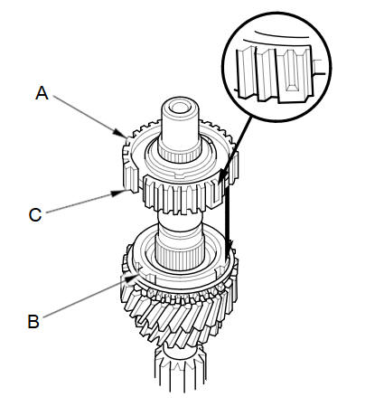
NOTE: Make sure to install the 3rd/4th synchro hub in the direction shown.
-
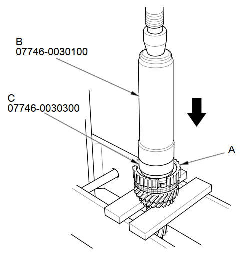
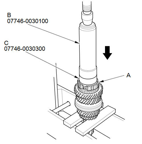
Press on the 3rd/4th synchro hub (A) using the 40 mm driver handle (B) and the 30 mm bearing driver attachment (C).
-
Install the 3rd/4th synchro sleeve (A) by aligning the stops (B) of the 3rd/4th synchro sleeve and the 3rd/4th synchro hub. After installation, check the operation of the 3rd/4th synchro hub set.
-
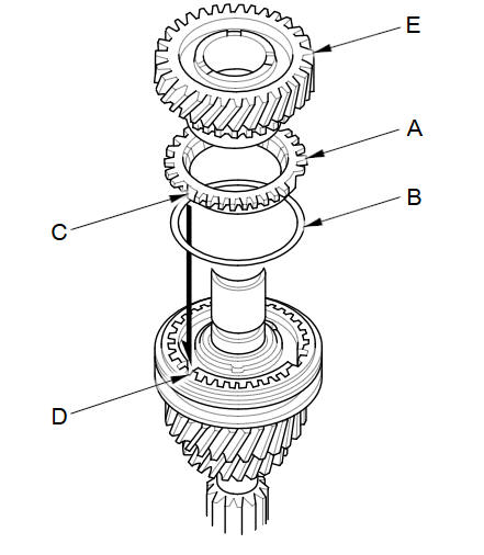
Install the synchro ring (A) with the synchro spring (B) by aligning the synchro ring fingers (C) with the grooves (D) in the 3rd/4th synchro hub.
-
Install 4th gear (E) onto the synchro ring.
-
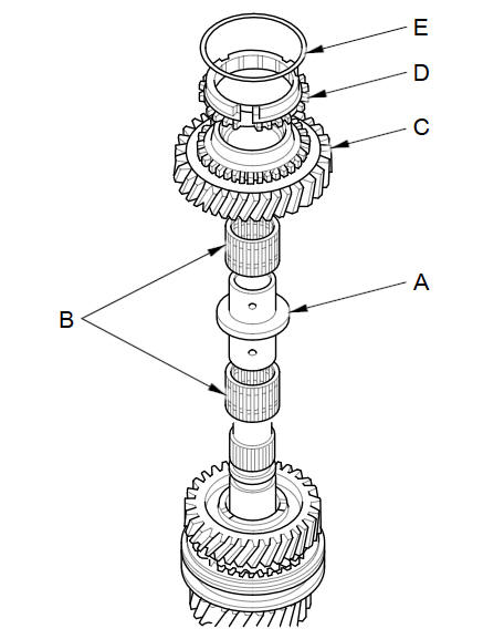
Install the 4th/5th gear distance collar (A) with the needle bearings (B) and 5th gear (C).
-
Install the synchro ring (D) with the synchro spring (E) onto 5th gear.
-
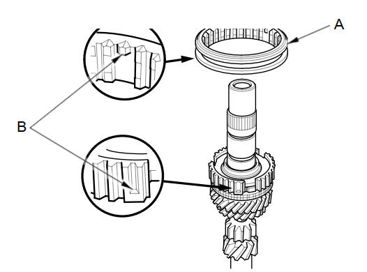
Install the 5th synchro hub (A) by aligning the synchro ring fingers (B) with the grooves (C) in the 5th synchro hub.
-
Press on the 5th synchro hub (A) using the 40 mm driver handle (B) and the 30 mm bearing driver attachment (C).
-
Install the 5th synchro sleeve (A) by aligning the slots of the 5th synchro sleeve and the 5th synchro hub (B). After installation, check the operation of the 5th synchro hub set.
NOTE: Make sure to align the slots in the 5th synchro hub as shown.
-
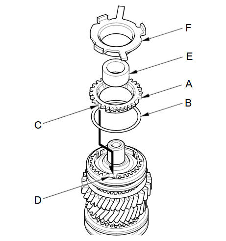
Install the synchro ring (A) with the synchro spring (B) by aligning the synchro ring fingers (C) with the grooves (D) in the 5th synchro hub.
-
Install the MBS distance collar (E) and the tapered cone ring (F).
-
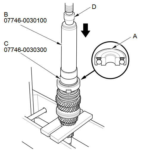
Press on a new angular ball bearing (A) using the 40 mm driver handle (B) the 30 mm bearing driver attachment (C), and a press (D).
See also:
Auxiliary Input Jack
U.S. Sport and all Canadian models
The auxiliary input jack is underneath the accessory power socket in the center
pocket. The system will accept auxiliary input from standard audio accessories.
...
Edit Avoid Area
INFO button
► Setup ►Other
►Routing & Guidance►Edit Avoid Area
“Edit”
Specify up to five areas to avoid (e.g., road construction, closures), if
possible, when
t ...
Removal
Drain the engine coolant.
Remove the air cleaner.
Remove the heater hose clamp bracket mounting bolt (A) and the harness
holder mounting bolt (B).
...
Categories
