Honda Fit: Hands Free Link Control Unit Input Test/Replacement
With navigation
-
Remove the driver's dashboard undercover.
-
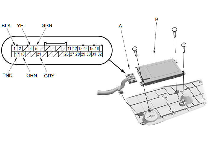
Disconnect the 32P connector (A) from the HandsFreeLink control unit (B).
-
Inspect the connector and socket terminals for a good pinfit to be sure they are all making good contact.
-
If the terminals are bent, loose or corroded, repair them as necessary, and recheck the system.
-
If the terminals look OK, go to step 4.
-
-
Reconnect the connector and make these input tests at the connector under the test conditions listed.
-
If any test indicates a problem, find and correct the cause, then recheck the system.
-
If all the input tests prove OK, go to 5.
Cavity
Wire color
Test condition
Test: Desired result
Possible cause if desired result is not obtained
1
BLK
Under all conditions
Measure the voltage to body ground:
There should be less than 0.2 V.
-
Poor ground (G501)
-
An open or high resistance in the wire
17
PNK
Under all conditions
Measure the voltage to body ground:
There should be battery voltage.
-
Blown No. B1 (15 A) fuse in the under-dash fuse/relay box
-
An open or high resistance in the wire
18
ORN
Ignition switch in ACCESSORY (I) or ON (II)
Measure the voltage to body ground:
There should be battery voltage.
-
Blown No. B14 (7.5 A) fuse in the under-dash fuse/relay box
-
An open or high resistance in the wire
-
-
Disconnect the 32P connector again, and make this input test at the connector.
-
If any test indicates a problem, find and correct the cause, then recheck the system.
-
If all the input tests prove OK, the HandsFreeLink control unit must be faulty; replace it.
Cavity
Wire color
Test condition
Test: Desired result
Possible cause if desired result is not obtained
4
·
5
YEL
·
GRN
Disconnect the audio-navigation unit connector C (14P)
Check for continuity to ground:
There should be no continuity.
Short to body ground in the wire(s)
4
·
5
·
21
YEL
·
GRN
·
GRY
Under all conditions
Check for continuity between No. 4 and No. 5, No. 4 and No. 21, and No. 5 and No. 21 terminals individually:
There should be no continuity.
A short in the wires
Disconnect the audio-navigation unit connector C (14P)
Check for continuity between No. 4 terminal and audio-navigation unit connector C (14P) terminal No. 9, No. 5 terminal and audio-navigation unit connector C (14P) terminal No. 10, and No. 21 terminal and audio-navigation unit connector C (14P) terminal No. 3 individually:
There should be continuity.
An open in the wire(s)
-
Without navigation
-
Remove the driver's dashboard undercover.
-
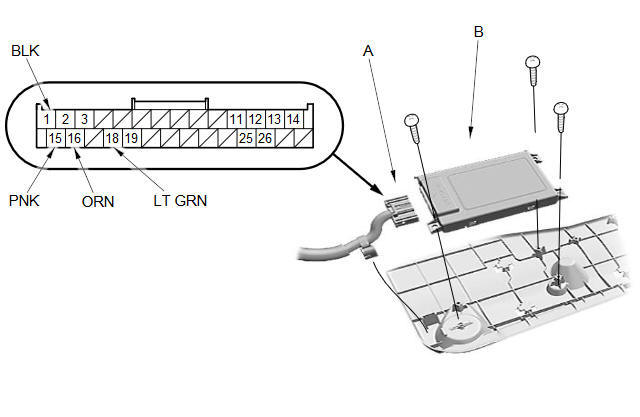
Disconnect the 28P connector (A) from the HandsFreeLink control unit (B).
-
Inspect the connector and socket terminals for a good pinfit to be sure they are all making good contact.
-
If the terminals are bent, loose or corroded, repair them as necessary, and recheck the system.
-
If the terminals look OK, go to step 4.
-
-
Reconnect the connector and make these input tests at the connector under the test conditions listed.
-
If any test indicates a problem, find and correct the cause, then recheck the system.
-
If all the input tests prove OK, go to 5.
Cavity
Wire color
Test condition
Test: Desired result
Possible cause if desired result is not obtained
14
BLK
Under all conditions
Measure the voltage to body ground:
There should be less than 0.2 V.
-
Poor ground (G501)
-
An open or high resistance in the wire
15
PNK
Under all conditions
Measure the voltage to body ground:
There should be battery voltage.
-
Blown No. B1 (15 A) fuse in the under-dash fuse/relay box
-
An open or high resistance in the wire
16
ORN
Ignition switch in ACCESSORY (I) or ON (II)
Measure the voltage to body ground:
There should be battery voltage.
-
Blown No. B14 (7.5 A) fuse in the under-dash fuse/relay box
-
An open or high resistance in the wire
-
-
Disconnect the 28P connector again, and make this input test at the connector.
-
If any test indicates a problem, find and correct the cause, then recheck the system.
-
If all the input tests prove OK, the HandsFreeLink control unit must be faulty; replace it.
Cavity
Wire color
Test condition
Test: Desired result
Possible cause if desired result is not obtained
18
ORN
Under all conditions
Check for continuity between No. 18 terminal and the under-dash fuse/relay box connector Q (16P) terminal No. 3:
There should be continuity.
An open in the wire
Disconnect these items:
-
Under-dash fuse/relay box connector Q (16P)
-
Gauge control module 32P connector
-
Immobilizer-keyless control unit 7P connector
Check for continuity to ground:
There should be no continuity.
Short to body ground in the wire
-
See also:
Installation (Part -2)
Set the front subframe (A) with the steering gearbox on the transmission jack and support it.
@font-face{font-family:
"Honda_SymbolMarkeng";src:url( ...
Reverse Shift Fork Clearance Inspection (M/T)
Measure the clearance between the reverse idler gear (A) and the reverse
shift fork (B) with a feeler gauge (C). If the clearance is more than the
service limit, go to step 2.
...
Childproof Door Locks
The childproof door locks prevent the rear doors from being opened from the
inside
regardless of the position of the lock tab.
To open the door from the inside when the
childproof door lock is on ...
Categories
