Honda Fit: Intake Manifold/Chamber Assembly Removal and Installation
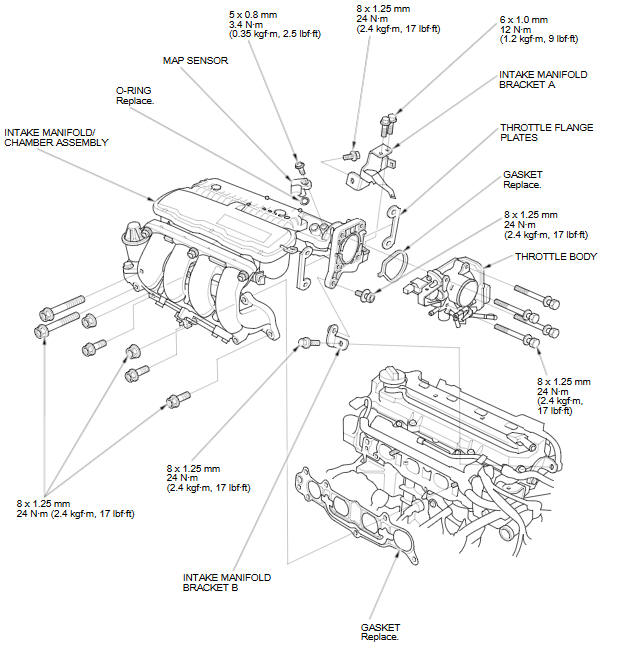
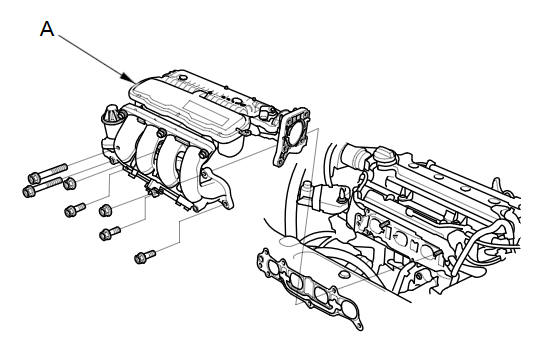
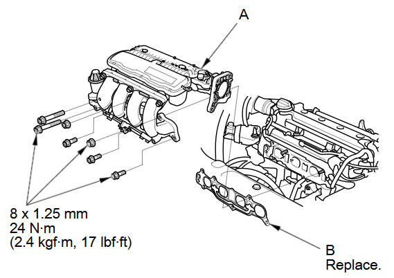
Exploded View
Removal
-
Remove the under-cowl panel.
-
Remove the air cleaner.
-
Disconnect the engine wire harness connectors, and remove the wire harness clamps from the intake manifold chamber:
-
Throttle actuator connector
-
MAP sensor connector
-
EGR valve connector
-
-
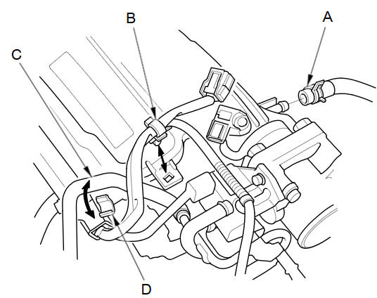
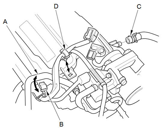
Disconnect the brake booster vacuum hose (A) and remove the harness clamp (B).
-
Remove the water bypass hose (C) from the clamp (D).
-
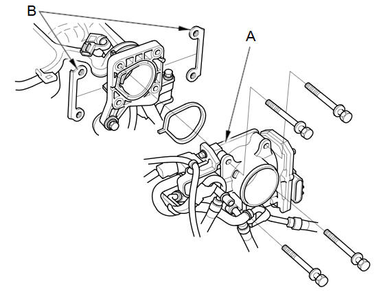
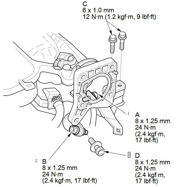
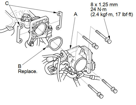
Remove the throttle body (A) without disconnecting the water bypass hoses.
-
Remove the throttle flange plates (B).
-
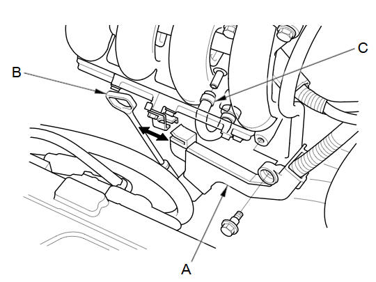
Remove the harness holder (A) and the dipstick (B).
-
Disconnect the PCV hose (C).
-
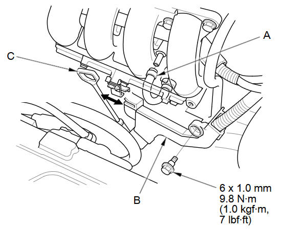
Remove the intake manifold bracket mounting bolts.
-
Remove the intake manifold/chamber assembly (A) from the cylinder head.
-
Disassemble the intake manifold/chamber assembly.
NOTE: Refer to the Exploded View if needed during this procedure.
Installation
-
Reassemble the intake manifold/chamber assembly.
NOTE: Refer to the Exploded View if needed during this procedure.
-
Install the intake manifold/chamber assembly (A) with a new gasket (B).
NOTE: Tighten the bolts and nuts in a crisscross pattern in three steps, beginning with the inner bolt.
-
Loosen the intake manifold bracket mounting bolts (A, B), then loosely install the intake manifold bracket mounting bolts (C, D).
-
Tighten the intake manifold bracket mounting bolts in the numbered sequence shown.
-
Install the throttle body (A) with a new gasket (B), and the throttle flange plates (C).
-
Connect the PCV hose (A).
-
Install the harness holder (B) and the dipstick (C).
-
Install the water bypass hose (A) to the clamp (B).
-
Connect the brake booster vacuum hose (C) and install the harness clamp (D).
-
Connect the engine wire harness connectors, and install the wire harness clamps to the intake manifold chamber:
-
Throttle actuator connector
-
MAP sensor connector
-
EGR valve connector
-
-
Install the air cleaner.
-
Install the under-cowl panel.
See also:
Introduction
Congratulations! Your selection of a 2008 Honda Fit was a wise investment.
It will give you years of driving pleasure.
One of the best ways to enhance the enjoyment of your new vehicle is to read
...
Valve Body and ATF Strainer Removal (A/T)
Remove the ATF feed pipe (A) from the regulator valve body (B).
Remove the ATF feed pipes (C) (D) from the servo body (E).
Remove the ATF strainer (F) (two bolts).
...
Disassembly
Compress the damper spring, then remove the nut (A) while holding the
damper shaft with a hex wrench (B). Do not compress the damper spring more
than necessary to remove the nut.
...
Categories
