Honda Fit: Countershaft Reassembly (M/T)
Exploded View
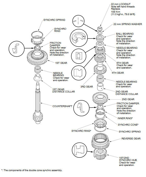
Special Tools Required
- Driver Handle, 40 mm I.D. 07746-0030100
- Bearing Driver Attachment, 25 mm I.D. 07746-0030200
- Bearing Driver Attachment, 30 mm I.D. 07746-0030300
- Bearing Driver Attachment, 35 mm I.D. 07746-0030400
NOTE: Refer to the Exploded View, as needed, during this procedure.
-
Clean all parts in solvent, dry them, and apply MTF to all contact surfaces.
-
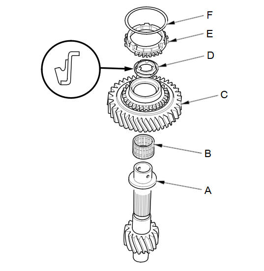
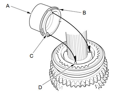
Install the 1st gear distance collar (A), with the needle bearing (B), 1st gear (C), and friction damper (D) on the shaft.
-
Install the 1st gear synchro ring (E) and synchro spring (F) on the shaft.
-
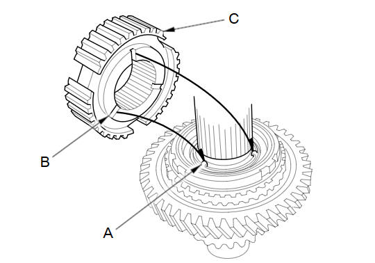
Align the fingers (A) on the friction damper with the grooves (B) on the 1st/2nd synchro hub (C), then install the 1st/2nd synchro hub onto the shaft.
-
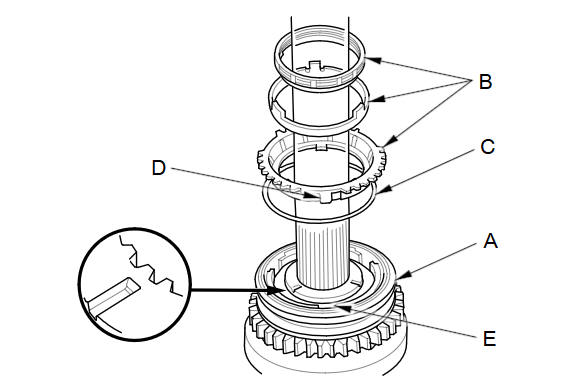
Install the reverse gear (A). Install the double cone synchro assembly (B) with the synchro spring (C) by aligning the synchro ring fingers (D) with the 1st/2nd synchro hub grooves (E).
-
Install the 2nd gear distance collar (A) and friction damper (B), then align the fingers (C) on the friction damper and the grooves (D) in the 1st/2nd synchro hub.
-
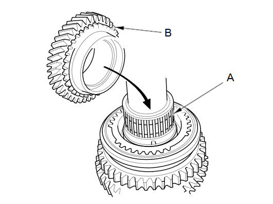
Install the needle bearing (A) and 2nd gear (B).
-
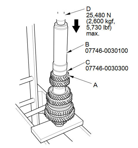
Support the countershaft (A) on steel blocks, then press on 3rd gear (B) using the 40 mm driver handle (C), 35 mm bearing driver attachment (D), and a press (E).
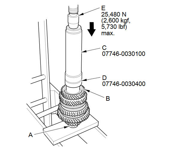
NOTE: Do not exceed the maximum pressure.
-
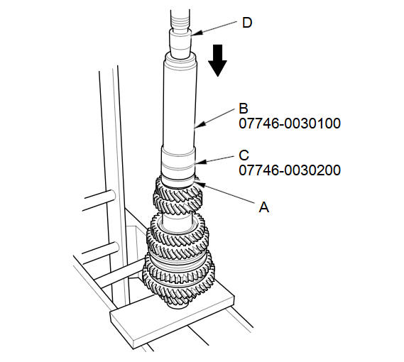
Press on 4th gear (A) using the 40 mm driver handle (B), 30 mm bearing driver attachment (C), and a press (D).
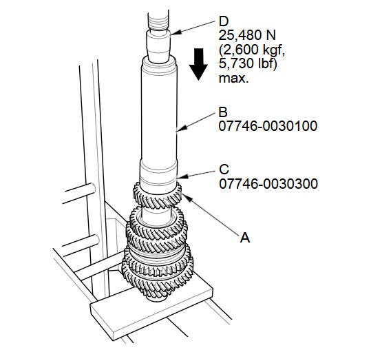
NOTE: Do not exceed the maximum pressure.
-
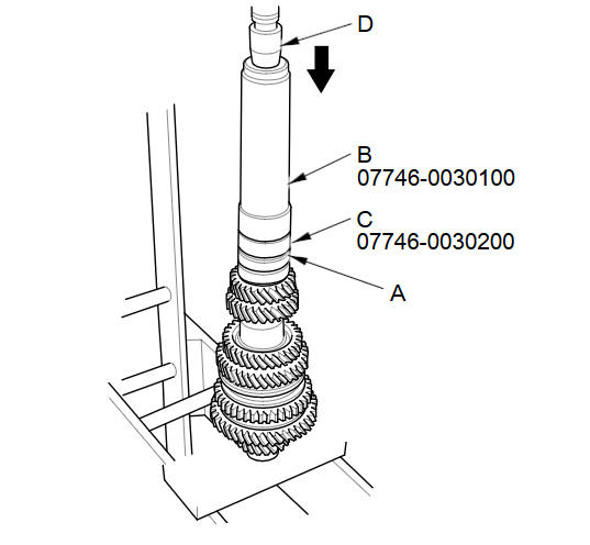
Press on 5th gear (A) using the 40 mm driver handle (B), 30 mm bearing driver attachment (C), and a press (D).
NOTE: Do not exceed the maximum pressure.
-
Press on the needle bearing (A) using the 40 mm driver handle (B), 25 mm bearing driver attachment (C), and a press (D).
-
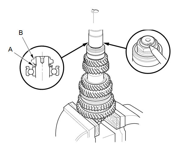
Press on the ball bearing (A) using the 40 mm driver handle (B), 25 mm bearing driver attachment (C), and a press (D).
-
Install the 22 mm spring washer (A) and a new 22 mm locknut (left-hand threads) (B).
-
Securely clamp the countershaft assembly in a bench vise with wood blocks.
-
Torque a new locknut to 108 NВ·m (11.0 kgfВ·m, 79.6lbfВ·ft), then loosen it and torque it again to the same value. Stake the locknut tab into the groove.
See also:
Gearshift Mechanism Replacement (M/T)
NOTE: Make sure not to get any silicone grease on the terminal part of the
connectors and switches, especially if you have silicone grease on your hands or
gloves.
...
Inspecting and Changing Fuses
1. Turn the ignition switch to LOCK
. Turn
headlights and all accessories off.
2. Check the fuses in the engine
compartment.
► If the fuse is blown, have it replaced by a
dealer.
3. I ...
Bluetooth® HandsFreeLink®
This section describes how to operate Bluetooth® HandsFreeLink®. You
can place and receive phone calls using your vehicle’s audio system
without handling your cell phone.
PHONE button
Select ...
Categories
