Honda Fit: Shift Solenoid Valve Removal and Installation (A/T)
NOTE: Do not hold the solenoid valve connector to remove and install the solenoid valve. Be sure to hold the solenoid valve body.
-
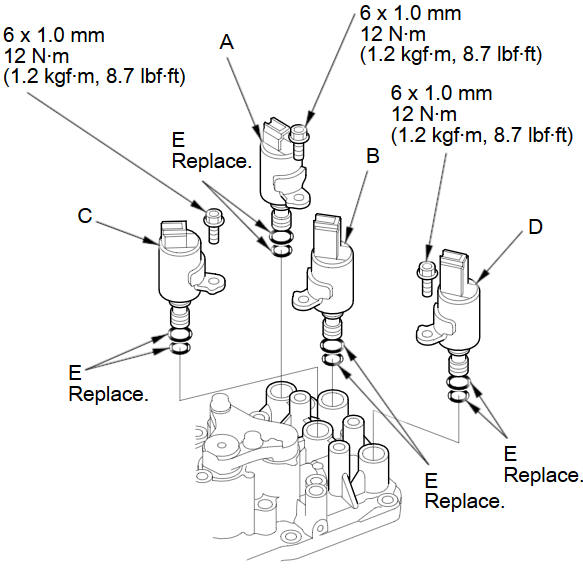
Remove the mounting bolts, then remove the solenoid valves by holding the solenoid valve body.
-
Install new O-rings (E) on each solenoid valve.
NOTE: A new solenoid valve comes with new O-rings. If you install a new solenoid valve, use the O-rings provided with it.
-
Install shift solenoid valve D (black connector) by holding the shift solenoid valve body; be sure the mounting bracket contacts to the servo body.
-
Install shift solenoid valve C (brown connector) by holding the shift solenoid valve body; be sure the mounting bracket contacts to the servo body.
-
Install shift solenoid valve B (black connector) by holding the shift solenoid valve body; be sure the mounting bracket contacts to the servo body.
-
Install shift solenoid valve A (brown connector) by holding the shift solenoid valve body; be sure the mounting bracket contacts to the bracket of shift solenoid valve B.
NOTE: Do not install shift solenoid valve A before installing shift solenoid valve B. If shift solenoid valve A is installed before installing shift solenoid valve B, it may damage the hydraulic control system.
See also:
Playing a USB Flash Drive
Your audio system reads and plays sound files on a USB flash drive in either
MP3,
WMA or AAC*1 format.
Connect your USB flash drive to the USB adapter cable, then press the AUX
button.
*1:O ...
Engine Coolant
Adding Engine Coolant
If the coolant level in the reserve tank is at or below the MIN line, add coolant
to bring it up to the MAX line.
Inspect the cooling system for leaks.
Always use Honda Lo ...
General Commands
Display menu (if en route, displays the
Route screen)
Display navigation (if en route, displays
the Route screen)
Display map
Display map guide (when en route,
shows the next guidance point)
Di ...
Categories
