Honda Fit: Valve Body and ATF Strainer Removal (A/T)
-
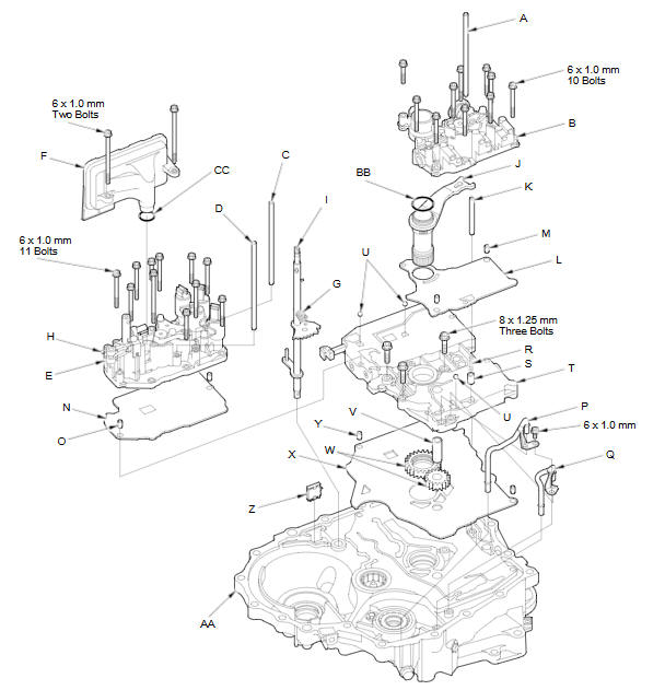
Remove the ATF feed pipe (A) from the regulator valve body (B).
-
Remove the ATF feed pipes (C) (D) from the servo body (E).
-
Remove the ATF strainer (F) (two bolts).
-
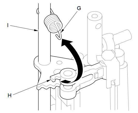
Unhook the detent spring (G) from the detent arm (H), and remove the control shaft (I).
-
Remove the regulator valve body (10 bolts).
-
Remove the stator shaft (J) and stator shaft stop (K), then remove the regulator separator plate (L) and two dowel pins (M).
-
Remove the servo body (11 bolts), then remove the separator plate (N) and two dowel pins (O).
-
Remove the ATF joint pipes (P) (Q).
-
Remove the cooler check valve spring (R) and cooler check valve (S), then remove the main valve body (T) (three bolts). Do not let the check balls (U) fall out.
-
Remove the ATF pump driven gear shaft (V), then remove the ATF pump gears (W).
-
Remove the main separator plate (X) and two dowel pins (Y).
-
Remove the ATF magnet (Z), clean and reinstall it in the torque converter housing (AA).
-
Remove the O-ring (BB) from the stator shaft, and remove the O-ring (CC) from the ATF strainer. Install new ones when installing the valve bodies.
-
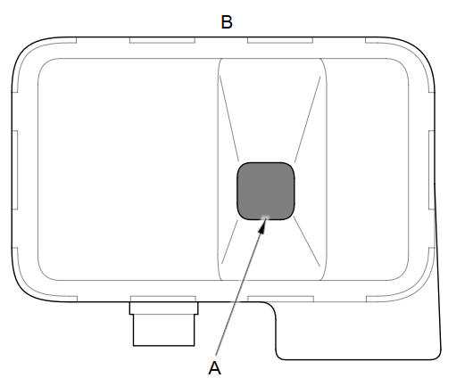
Clean the inlet opening (A) of the ATF strainer (B) thoroughly with compressed air, then check that it is in good condition and that the inlet opening is not clogged.
-
Test the ATF strainer by pouring clean ATF through the inlet opening, and replace it if it is clogged or damaged.
See also:
Engine Coolant
Adding Engine Coolant
If the coolant level in the reserve tank is at or below the MIN line, add coolant
to bring it up to the MAX line.
Inspect the cooling system for leaks.
Always use Honda Lo ...
Correct Vehicle Position
INFO button
► Setup ►Other
►Vehicle
Manually adjust the current position of the vehicle as displayed on the map
screen if
the position appears to be incorrect.
1. Put the v ...
Piston Installation
If the Crankshaft is Already Installed
Set the crankshaft to bottom dead center (BDC) for each cylinder as its
piston is installed.
Remove the connecting rod caps, and check that ...
Categories
