Honda Fit: Automatic Transmission Removal (A/T)
Special Tools Required
- Universal Lifting Eyelet 07AAK-SNAA120
- 1.8 Support Bolt 07AAK-SNAA500
- Engine Support Hanger, A and Reds AAR-T1256
*: Reds engine support hanger AAR-T1256 is available through the Honda Tool and Equipment Program 888-424-6857.
SRS components are located in this area. Review the SRS component locations and the precautions and procedures before doing repairs or service.
NOTE:
-
Use fender covers to avoid damaging painted surfaces.
-
Special tool Reds engine support hanger AAR-T1256 must be used with the side engine mount installed.
-
Remove the steering wheel.
-
Remove the steering joint cover (A).

-
Make a reference mark (B) across the steering joint and the steering gearbox pinion shaft. Remove the steering joint bolt (C), and disconnect the steering joint (D) by removing the steering joint toward the steering column. Hold the slider shaft (E) on the column with a piece of wire (F) between the joint yoke (G) on the slider shaft to the joint yoke on the upper shaft.
-
Remove the battery base.
-
Remove the cowl cover.
-
Fix the hood in a vertical position.
-
Remove the windshield wiper motor (A).
-
Remove the cowl cover stiffener (B) and center-front cowl cover (C).
-
Remove the air cleaner assembly.
-
Raise the vehicle on a lift, and make sure it is securely supported.
-
Remove the wheels.
-
Remove the splash shield.
-
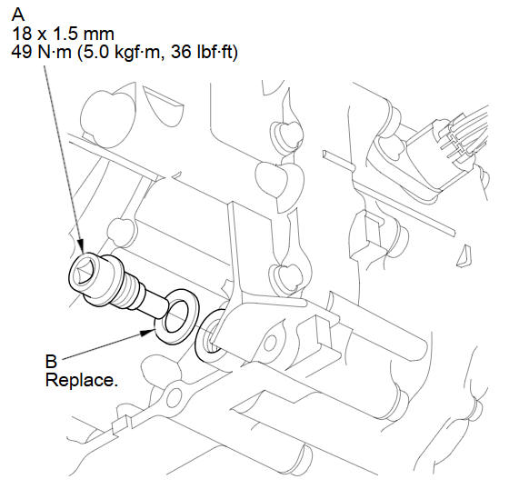
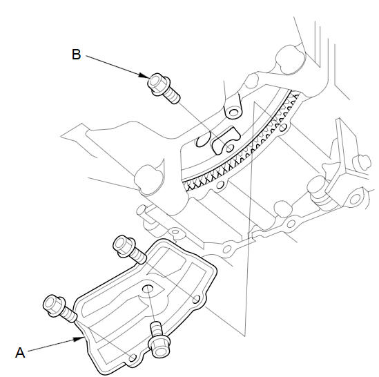
Remove the drain plug (A), and drain the automatic transmission fluid (ATF).
-
Reinstall the drain plug with a new sealing washer (B).
-
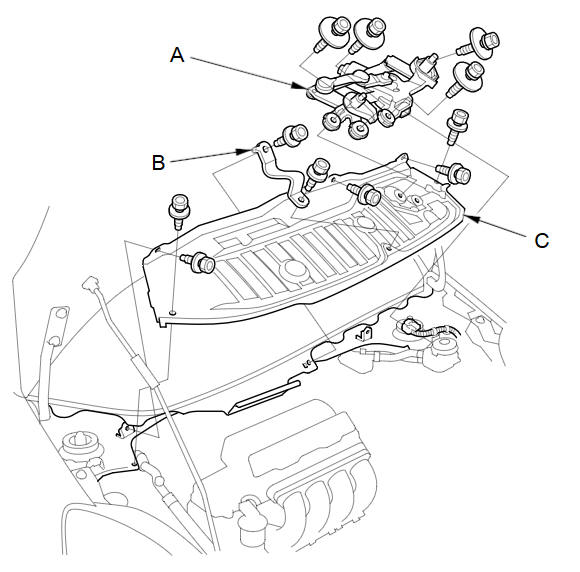
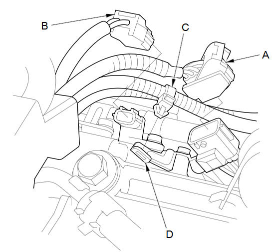
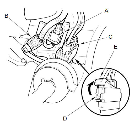
Disconnect the A/T clutch pressure control solenoid valve A connector (A), the A/T clutch pressure control solenoid valve B connector (B), and the A/T clutch pressure control solenoid valve C connector (C).
-
Remove the bolt securing the harness cover (D), and remove the harness cover from its bracket (E).
-
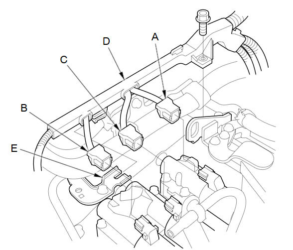
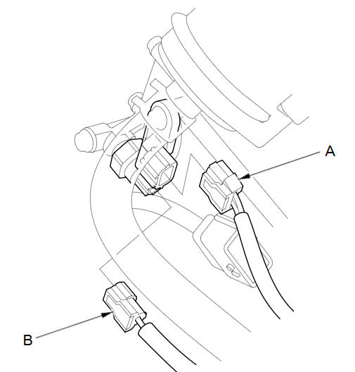
Disconnect the transmission range switch connector (A).
-
Disconnect the output shaft (countershaft) speed sensor connector (B), and remove the harness clamp (C) from its bracket (D).
-
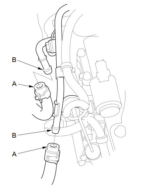
Disconnect the input shaft (mainshaft) speed sensor connector (A) and the transmission fluid pressure switch A (2nd clutch) connector (B).
-
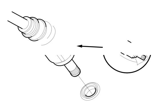
Remove the ATF cooler hoses (A) from the ATF cooler lines (B). Turn the ends of the cooler hoses up to prevent ATF from flowing out, then plug the cooler hoses and lines.
-
Check for any signs of leakage at the hose joints.
-
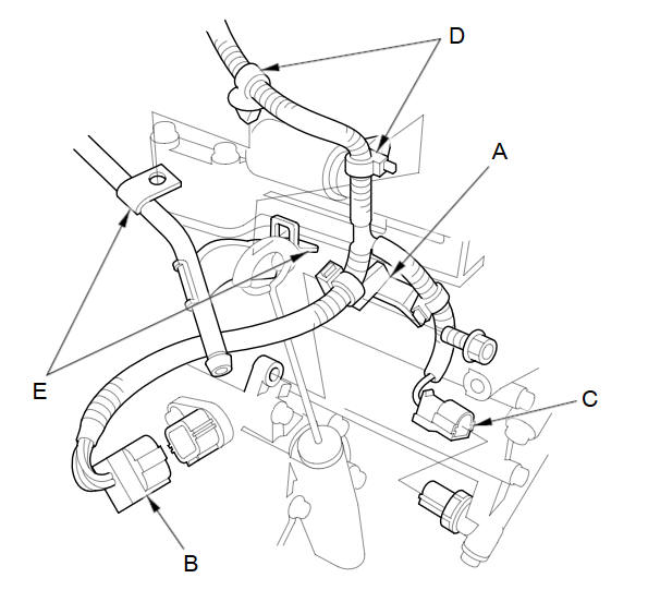
Remove the bolt securing the harness clamp bracket (A).
-
Disconnect the shift solenoid harness connector (B) and the transmission fluid pressure switch B (3rd clutch) connector (C), and remove the harness clamps (D) from the clamp brackets (E).
-
Remove the air cleaner housing mounting bracket from the transmission hanger.
-
Disconnect the EPS motor angle sensor 8P connector (A) and torque sensor 6P connector (B) from the steering gearbox.
-
Disconnect the EPS motor 3P connector (C) by pushing the lock (D) and pulling up the lever (E).
-
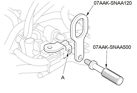
Install the universal lifting eyelet (07AAK-SNAA120) to the bolt hole (A) at the air cleaner housing mounting bracket with the 1.8 support bolt (07AAK-SNAA500).
-
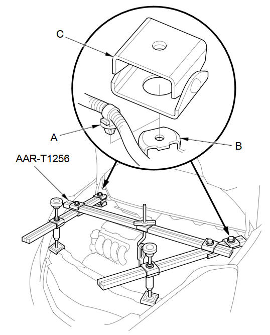
Remove the harness clamp (A) from its clamp bracket (B) located in front of the left damper top.
-
Set up the engine support hanger (AAR-T1256). Carefully position the engine support hanger to the vehicle; position both cross-arm foot bases (C) over the harness clamp brackets on both sides, and position both front stands on the front bulkhead. Attach the hook to the universal eyelet, tighten the wing nut by hand, and lift and support the engine.
-
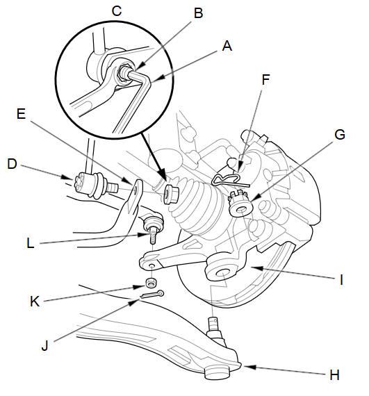
Insert a 5 mm Allen wrench (A) in the top of the ball joint pin (B), and remove the nuts (C), then separate the stabilizer link (D) from the stabilizer ends (E).
-
Remove the spring clips (F) and castle nuts (G), and separate the lower arms (H) from the knuckles (I).
-
Remove the cotter pins (J) and the nuts (K), and separate the tie-rod end ball joint (L) from the knuckles.
-
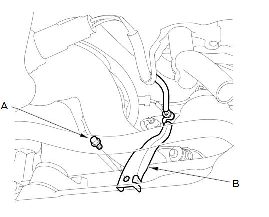
Remove the 6.0 mm bolt (A) securing the secondary HO2S wire clamp (B) on the steering gearbox. Do not disconnect secondary HO2S 4P connector and secondary HO2S.
-
Remove the shift cable cover.
-
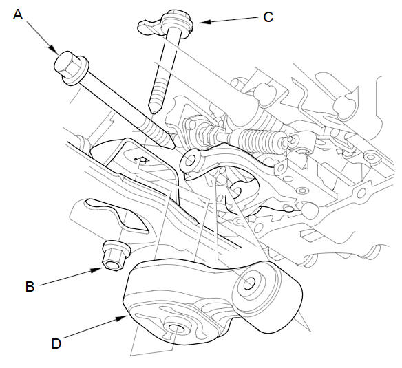
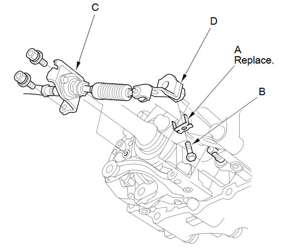
Place a jack under the transmission, raise it just enough to take it off of the lower torque rod, and remove the lower torque rod bolt (A) on the transmission.
-
Remove the lower torque rod nut (B) and bolt (C) on the front subframe, and remove the lower torque rod (D).
-
Remove the jack.
-
Support the front subframe with a jack.
-
Remove the six bolts securing the front subframe.
-
Lower the front subframe and steering gearbox as an assembly by lowering the jack slowly.
-
Pry up the lock tab of the lock washer (A), and remove the lock bolt (B) and the lock washer.
-
Remove the bolts securing the shift cable holder (C), and separate the shift cable (D) from the selector control shaft end. Do not bend the shift cable excessively.
-
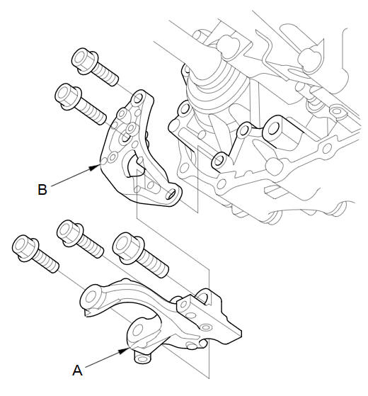
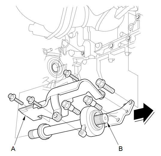
Remove the lower torque rod mounting bracket (A) and the shift cable holder bracket (B).
-
Remove the torque converter cover (A), and remove the drive plate bolts (B) (eight bolts) while rotating the crankshaft pulley.
-
Pry out the driveshafts from the differential and the intermediate shaft.
-
Coat all precision machined surfaces with clean engine oil, then put plastic bags over driveshaft ends.
-
Remove the bolts securing the heat shield (A).
-
Remove the intermediate shaft (B) and the heat shield.
-
Coat all precision finished surfaces with clean engine oil, then put plastic bags over intermediate shaft ends.
-
Remove the front and upper transmission housing mounting bolts.
-
Remove the transmission ground cable terminal (A) from the transmission mount bracket (B).
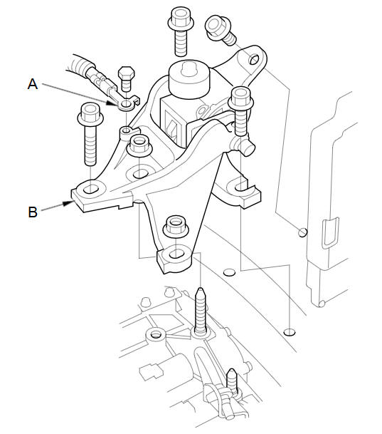
-
Place a jack under the transmission, raise it just enough to take it off of the mount, and remove the transmission mount and mount bracket.
-
Remove the jack.
-
Remove the rear transmission housing mounting bolts.
-
Lower the transmission by loosening the wing nut on the engine support hanger, and tilt the engine just enough for the end of the transmission to clear the side frame.
-
Place a jack under the transmission.
-
Remove the lower transmission housing mounting bolts.
-
Slide the transmission away from the engine to remove it from the vehicle.
-
Remove the torque converter and the dowel pins.
-
Inspect the drive plate, and replace it if it's damaged.
See also:
ATF Replacement (A/T)
NOTE: Keep all foreign particles out of the transmission.
Warm up the engine to normal operating temperature (the radiator fan
comes on), and turn the engine off.
Raise the vehic ...
Customer Service Information
Honda dealership personnel are trained professionals.
They should be able to answer all your questions. If you encounter a problem
that
your dealership does not solve to your satisfaction, pleas ...
Listening to Voice Guidance
MAP MENU (on map)
► VOICE
As you approach each guidance point, a pop-up window is displayed on the map
screen with instructions for you to follow. Voice guidance for each guidance
point is ...
Categories
