Honda Fit: Starting System
Starter Overhaul
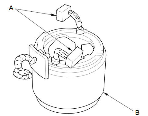
Exploded View
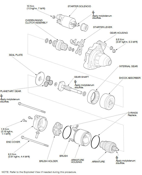
NOTE: Refer to the Exploded View if needed during this procedure.
Armature Inspection and Test
-
Remove the starter.
-
Inspect the armature for wear or damage from contact with the permanent magnet. If there is wear or damage, replace the armature.
-
Check the commutator (A) surface. If the surface is dirty or burnt, resurface it with an emery cloth or a lathe to the specifications in step 4, or recondition with #500 or #600 sandpaper (B).
-
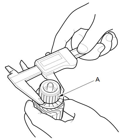
Check the commutator (A) diameter with a digital caliper or daial type caliper. If the diameter is below the service limit, replace the armature.
Commutator Diameter
Standard (New):
28.0 mm (1.102 in)
Service Limit:
27.0 mm (1.063 in)
-
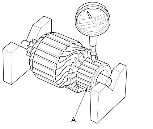
Measure the commutator (A) runout:
-
If the commutator runout is within the service limit, check the commutator for carbon dust or brass chips between the segments.
-
If the commutator runout is not within the service limit, replace the armature.
Commutator Runout
Standard (New):
0.02 mm (0.0008 in) max.
Service Limit:
0.05 mm (0.0020 in)
-
-
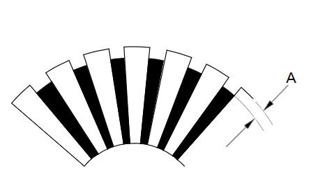
Use a digital caliper or dial type caliper to check the mica depth (A). If the mica depth is below the service limit, replace the armature.
Commutator Mica Depth
Standard (New):
0.50пјЌ0.80 mm (0.0197пјЌ0.0315 in)
Service Limit:
0.20 mm (0.0079 in)
-
Use an ohmmeter to check for continuity between the segments of the commutator. If there is an open circuit between any segments, replace the armature.
-
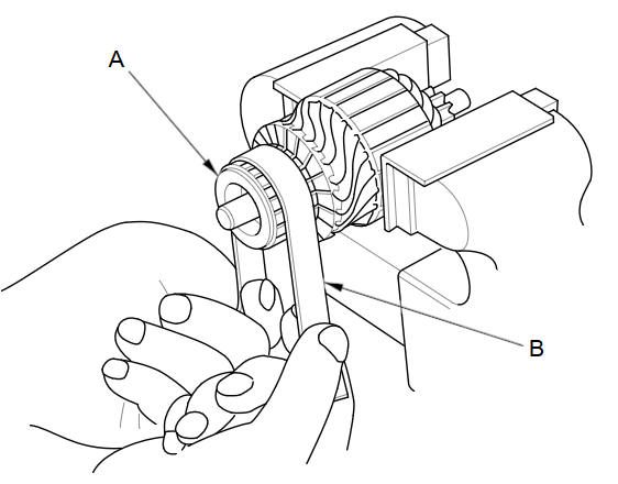
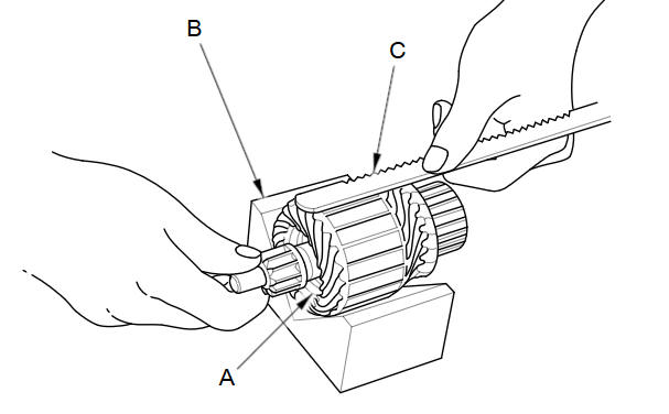
Place the armature (A) on an armature tester (B). Hold a hacksaw blade (C) on the armature core. If the blade is attracted to the core while the core is turned, the armature is shorted. Replace the armature.
-
Use an ohmmeter to check for continuity between the commutator (A) and the armature coil core (B), and between the commutator and the armature shaft (C). If there is continuity, replace the armature.
Starter Brush Inspection
-
Measure the brush length. If it is shorter than the service limit, replace the brush holder assembly.
Brush Length
Standard (New):
14.0пјЌ14.5 mm (0.551пјЌ0.571 in)
Service Limit:
9.0 mm (0.354 in)
Starter Field Winding Test
-
Check for continuity between the brushes (A). If there is no continuity, replace the armature housing (B).
-
Check for continuity between each brush and the armature housing. If there is continuity, replace the armature housing.
Starter Brush Holder Test
-
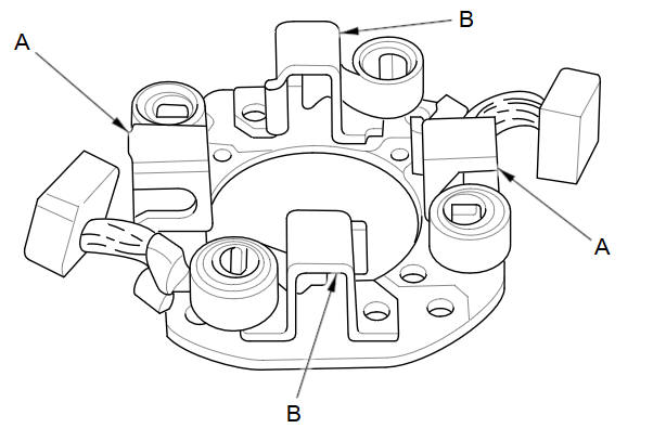
Check for continuity between the (пј‹) brush holders (A) and the (пјЌ) brush holders (B). If there is continuity, replace the brush holder assembly.
Brush Spring Inspection
-
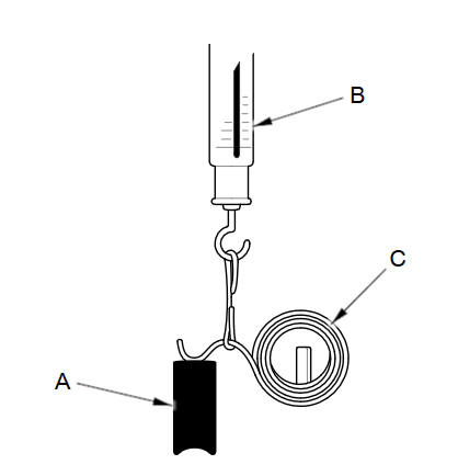
Insert the brush (A) into the brush holder, and bring the brush into contact with the commutator, then attach a spring scale (B) to the spring (C). Measure the spring tension at the moment the spring lifts off the brush. If it is not within the standard, replace the brush holder assembly.
Spring Tension
Standard (New):
13.73пјЌ17.65 N (1.400пјЌ1.800 kgf, 3.086пјЌ3.968 lbf)
Overrunning Clutch Inspection
-
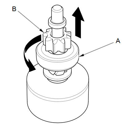
Slide the overrunning clutch (A) along the shaft. If it does not slide smoothly, replace it.
-
Hold the drive gear (B), and turn the overrunning clutch in the direction shown to make sure it turns freely. Also make sure the overrunning clutch locks in the opposite direction. If it does not lock in either direction or it locks in both directions, replace it.
-
If the starter drive gear is worn or damaged, replace the overrunning clutch assembly; the gear is not available separately. Check the condition of the flywheel ring gear (M/T model) or the torque converter ring gear (A/T model). If the starter drive gear teeth are damaged, replace it.
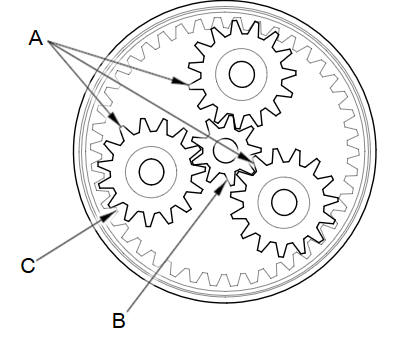
Planetary Gear Inspection
-
Check the planetary gears (A), the armature shaft gear (B), and internal ring gear (C). If they are worn or damaged, replace them.
Starter Reassembly
-
Pry back each brush spring with a flat-blade screwdriver, then position the brush on the brush holder about halfway out of its holder. Release the spring to hold it in place.
NOTE: To seat new brushes. Slip a strip of #500 or #600 sandpaper, with the grit side up, between the commutator and each brush, and smoothly turn the armature. The contact surface of the brushes will be sanded to the same contour as the commutator.
-
Install the armature in the housing, and install the brush holder. Next, pry back each brush spring again, and push the brush down until it seats against the commutator, then release the spring against the end of the brush.
-
Install the starter end cover to retain the brush holder.
-
Install the starter.
See also:
Reset Factory Default Settings
INFO button
► Setup ►Other
►Reset Factory Default
Reset all the settings on the Setup screens to their factory defaults.
Select Yes.
The following settings are reset:
• Br ...
Rectifier Test
Check for continuity in each direction, between the B terminal and P terminals,
and between the E terminal and P terminals of each diode pair. All diodes should
have continuity in only one ...
Vehicle Storage
If you need to park your vehicle for an extended period (more than 1 month),
there are several things you should do to prepare it for storage.
Proper preparation helps prevent deterioration and mak ...
Categories
