Honda Fit: Hands Free Link Control Unit Input Test/Replacement
With navigation
-
Remove the driver's dashboard undercover.
-
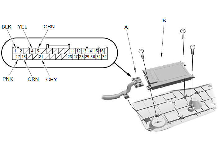
Disconnect the 32P connector (A) from the HandsFreeLink control unit (B).
-
Inspect the connector and socket terminals for a good pinfit to be sure they are all making good contact.
-
If the terminals are bent, loose or corroded, repair them as necessary, and recheck the system.
-
If the terminals look OK, go to step 4.
-
-
Reconnect the connector and make these input tests at the connector under the test conditions listed.
-
If any test indicates a problem, find and correct the cause, then recheck the system.
-
If all the input tests prove OK, go to 5.
Cavity
Wire color
Test condition
Test: Desired result
Possible cause if desired result is not obtained
1
BLK
Under all conditions
Measure the voltage to body ground:
There should be less than 0.2 V.
-
Poor ground (G501)
-
An open or high resistance in the wire
17
PNK
Under all conditions
Measure the voltage to body ground:
There should be battery voltage.
-
Blown No. B1 (15 A) fuse in the under-dash fuse/relay box
-
An open or high resistance in the wire
18
ORN
Ignition switch in ACCESSORY (I) or ON (II)
Measure the voltage to body ground:
There should be battery voltage.
-
Blown No. B14 (7.5 A) fuse in the under-dash fuse/relay box
-
An open or high resistance in the wire
-
-
Disconnect the 32P connector again, and make this input test at the connector.
-
If any test indicates a problem, find and correct the cause, then recheck the system.
-
If all the input tests prove OK, the HandsFreeLink control unit must be faulty; replace it.
Cavity
Wire color
Test condition
Test: Desired result
Possible cause if desired result is not obtained
4
·
5
YEL
·
GRN
Disconnect the audio-navigation unit connector C (14P)
Check for continuity to ground:
There should be no continuity.
Short to body ground in the wire(s)
4
·
5
·
21
YEL
·
GRN
·
GRY
Under all conditions
Check for continuity between No. 4 and No. 5, No. 4 and No. 21, and No. 5 and No. 21 terminals individually:
There should be no continuity.
A short in the wires
Disconnect the audio-navigation unit connector C (14P)
Check for continuity between No. 4 terminal and audio-navigation unit connector C (14P) terminal No. 9, No. 5 terminal and audio-navigation unit connector C (14P) terminal No. 10, and No. 21 terminal and audio-navigation unit connector C (14P) terminal No. 3 individually:
There should be continuity.
An open in the wire(s)
-
Without navigation
-
Remove the driver's dashboard undercover.
-
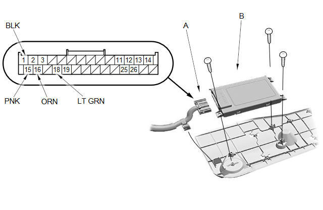
Disconnect the 28P connector (A) from the HandsFreeLink control unit (B).
-
Inspect the connector and socket terminals for a good pinfit to be sure they are all making good contact.
-
If the terminals are bent, loose or corroded, repair them as necessary, and recheck the system.
-
If the terminals look OK, go to step 4.
-
-
Reconnect the connector and make these input tests at the connector under the test conditions listed.
-
If any test indicates a problem, find and correct the cause, then recheck the system.
-
If all the input tests prove OK, go to 5.
Cavity
Wire color
Test condition
Test: Desired result
Possible cause if desired result is not obtained
14
BLK
Under all conditions
Measure the voltage to body ground:
There should be less than 0.2 V.
-
Poor ground (G501)
-
An open or high resistance in the wire
15
PNK
Under all conditions
Measure the voltage to body ground:
There should be battery voltage.
-
Blown No. B1 (15 A) fuse in the under-dash fuse/relay box
-
An open or high resistance in the wire
16
ORN
Ignition switch in ACCESSORY (I) or ON (II)
Measure the voltage to body ground:
There should be battery voltage.
-
Blown No. B14 (7.5 A) fuse in the under-dash fuse/relay box
-
An open or high resistance in the wire
-
-
Disconnect the 28P connector again, and make this input test at the connector.
-
If any test indicates a problem, find and correct the cause, then recheck the system.
-
If all the input tests prove OK, the HandsFreeLink control unit must be faulty; replace it.
Cavity
Wire color
Test condition
Test: Desired result
Possible cause if desired result is not obtained
18
ORN
Under all conditions
Check for continuity between No. 18 terminal and the under-dash fuse/relay box connector Q (16P) terminal No. 3:
There should be continuity.
An open in the wire
Disconnect these items:
-
Under-dash fuse/relay box connector Q (16P)
-
Gauge control module 32P connector
-
Immobilizer-keyless control unit 7P connector
Check for continuity to ground:
There should be no continuity.
Short to body ground in the wire
-
See also:
Warranty Coverages
■ U.S. Owners
Your new vehicle is covered by these warranties:
New Vehicle Limited Warranty – covers your new vehicle, except for the
emissions control systems and accessories, against defe ...
Playing an iPod®
■Connecting an iPod®
1. Unclip the USB connector in the center console and loosen the adapter
cable.
2. Install the iPod® dock connector to the USB connector.
• Do not use an extensio ...
Rear Stabilizer Bushing Replacement
Raise and support the vehicle.
Remove the stabilizer bushing (A) from the axle beam.
@font-face{font-family:
"Honda_SymbolMarkeng";src:url(/st ...
Categories
