Honda Fit: Servo Body Disassembly, Inspection, and Reassembly (A/T)
-
Clean all parts thoroughly in solvent, and dry them with compressed air. Blow out all passages.
-
Inspect the servo body for scoring and damage.
-
Check all valves for free movement. If any fail to slide freely, refer to valve body repair.
-
Coat all parts with ATF during assembly.
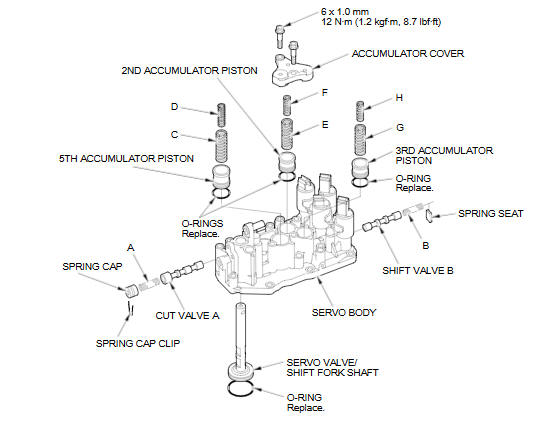
VALVE SPRINGS SPECIFICATIONS
|
Valve Springs |
Standard (New)-Unit: mm (in) |
||||
|
Wire Diameter |
O.D. |
Free Length |
No. of Coils |
||
|
A |
Cut valve A spring |
0.9 (0.035) |
9.9 (0.390) |
22.3 (0.878) |
6.9 |
|
B |
Shift valve B spring |
0.8 (0.031) |
7.1 (0.280) |
23.7 (0.933) |
9.7 |
|
C |
5th accumulator spring A |
2.5 (0.098) |
16.6 (0.654) |
46.9 (1.846) |
7.8 |
|
D |
5th accumulator spring B |
1.9 (0.075) |
10.0 (0.394) |
38.5 (1.516) |
10.6 |
|
E |
2nd accumulator spring A |
1.8 (0.071) |
14.6 (0.575) |
43.8 (1.724) |
7.9 |
|
F |
2nd accumulator spring B |
1.85 (0.073) |
9.4 (0.370) |
32.5 (1.280) |
8.7 |
|
G |
3rd accumulator spring A |
1.8 (0.071) |
14.6 (0.575) |
43.8 (1.724) |
7.9 |
|
H |
3rd accumulator spring B |
1.85 (0.073) |
9.4 (0.370) |
32.5 (1.280) |
8.7 |
See also:
Rectifier Test
Check for continuity in each direction, between the B terminal and P terminals,
and between the E terminal and P terminals of each diode pair. All diodes should
have continuity in only one ...
Output Shaft (Countershaft) Speed Sensor Replacement (A/T)
Remove the air cleaner assembly.
Disconnect the output shaft (countershaft) speed sensor connector, and
remove the output shaft (countershaft) speed sensor (A).
...
Auxiliary Input Jack
Use the jack in the console compartment to connect standard audio devices.
1. Open the AUX cover.
2. Connect a standard audio device to
the input jack using a 1/8 inch/3.5
mm stereo miniplug.
& ...
Categories
