Honda Fit: Fuel and Emissions System Description - Electronic Control System
Electronic Control Systems
The functions of the fuel and emission control systems are managed by the engine control module (ECM) on vehicles with manual transmissions or the powertrain control module (PCM) on vehicles with automatic transmissions.
Self-diagnosis
The ECM/PCM detects the failure of a signal from a sensor or from another control unit and stores a Pending DTC or a Confirmed DTC. Depending on the failure, a Confirmed DTC is stored in either the first or the second drive cycle. When a Confirmed DTC is stored, the ECM/PCM turns on the malfunction indicator lamp (MIL) by a signal sent to the gauge control module via F-CAN.
-
One Drive Cycle Detection Method
When an abnormality occurs in the signal from a sensor or from another control unit, the ECM/PCM stores a Confirmed DTC for the failure and turns on the MIL immediately.
-
Two Drive Cycle Detection Method
When an abnormality occurs in the signal from a sensor or from another control unit in the first drive cycle, the ECM/PCM stores a Pending DTC. The MIL does not come on at this time. If the failure continues in the second drive cycle, the ECM/PCM stores a Confirmed DTC and turns on the MIL.
Fail-safe Function
When an abnormality occurs in the signal from a sensor or from another control unit, the ECM/PCM ignores that signal and substitutes a pre-programmed value for it them that allows the engine to continue running. This causes a DTC to be stored and the MIL to come on.
MIL Bulb Check and Readiness Code Condition
When the ignition switch is turned to ON (II), the ECM/PCM turns on the MIL via the F-CAN circuit for about 15 to 20 seconds to check the bulb condition. If any readiness codes are not set to complete, the MIL flashes five times. If all readiness codes are set to complete, the MIL goes off.
Self Shut Down (SSD) Mode
After the ignition switch is turned to ACCESSORY (I) or to LOCK (0), the ECM/PCM stays on for up to an hour. If an ECM/PCM connector is disconnected during this time, the ECM/PCM may be damaged. To cancel this mode, disconnect the negative cable from the battery, or jump the SCS line with the HDS after the ignition switch is turned to ACCESSORY (I) or LOCK (0).

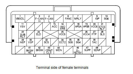
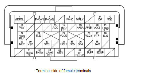
ECM/PCM Inputs and Outputs at ECM/PCM Connector A (49P)
|
Terminal number |
Wire color |
Terminal name |
Description |
Signal |
|
1*1 |
BRN |
VBSOL (POWER SOURCE FOR SOLENOID VALVES) |
Power source for solenoid valves |
With ignition switch ON (II): battery voltage |
|
3 |
WHT |
F-CAN H (CAN COMMUNICATION SIGNAL HIGH) |
Sends communication signal |
With ignition switch ON (II): about 2.5 V (pulses) |
|
4 |
RED |
F-CAN L (CAN COMMUNICATION SIGNAL LOW) |
Sends communication signal |
With ignition switch ON (II): about 2.5 V (pulses) |
|
6 |
GRN |
FANC (RADIATOR FAN CONTROL) |
Drives radiator fan relay or A/C condenser fan relay |
With radiator fan or A/C condenser fan running: about 0 V With radiator fan or A/C condenser fan stopped: battery voltage |
|
7 |
BLU |
MRLY (PGM-FI MAIN RELAY 1) |
Drives PGM-FI main relay 1 |
With ignition switch ON (II): about 0 V With ignition switch in LOCK (0): battery voltage |
|
9 |
LT GRN |
IGP (POWER SOURCE) |
Power source for ECM/PCM circuit |
With ignition switch ON (II): battery voltage |
|
10 |
YEL |
SG6 (SENSOR GROUND) |
Sensor ground |
Less than 0.2 V at all times |
|
11 |
RED |
VSV (EVAPORATIVE EMISSION (EVAP) CANISTER VENT SHUT VALVE) |
Drives EVAP canister vent shut valve |
With ignition switch ON (II): battery voltage |
|
15 |
PNK |
ACC (A/C COMPRESSOR CLUTCH RELAY) |
Drives A/C compressor clutch relay |
With compressor ON: about 0 V With compressor OFF: battery voltage |
|
16 |
BRN |
IMOFPR (IMMOBILIZER FUEL PUMP RELAY) |
Drives PGM-FI main relay 2 |
About 0 V for 2 seconds after turning ignition switch ON (II), then battery voltage With the engine running: about 0 V |
|
18 |
ORN |
APSA (ACCELERATOR PEDAL POSITION (APP) SENSOR A) |
Detects APP sensor A signal |
With ignition switch ON (II) and accelerator pedal pressed: about 4.5 V With ignition switch ON (II) and accelerator pedal released: about 1.0 V |
|
19 |
LT BLU |
APSB (ACCELERATOR PEDAL POSITION (APP) SENSOR B) |
Detects APP sensor B signal |
With ignition switch ON (II) and accelerator pedal pressed: about 2.3 V With ignition switch ON (II) and accelerator pedal released: about 0.5 V |
|
20 |
WHT |
VCC6 (SENSOR VOLTAGE) |
Provides sensor reference voltage |
With ignition switch ON (II): about 5.0 V |
|
21 |
RED |
ETCSRLY (ELECTRONIC THROTTLE CONTROL SYSTEM (ETCS) CONTROL RELAY) |
Drives electronic throttle control system (ETCS) control relay |
With ignition switch ON (II): about 0 V |
|
22 |
ORN |
SUBRLY (PGM-FI SUBRELAY) |
Drives A/F sensor relay |
With ignition switch ON (II): about 0 V |
|
24 |
PNK |
ELD (ELECTRICAL LOAD DETECTOR (ELD)) |
Detects ELD signal |
With ignition switch ON (II): about 0.1пјЌ4.8 V (depending on electrical load) |
|
*1: |
A/T |
ECM/PCM Inputs and Outputs at ECM/PCM Connector A (49P)
|
Terminal number |
Wire color |
Terminal name |
Description |
Signal |
|
25 |
GRY |
VCC5 (SENSOR VOLTAGE) |
Provides sensor reference voltage |
With ignition switch ON (II): about 5.0 V |
|
26 |
BRN |
VCC4 (SENSOR VOLTAGE) |
Provides sensor reference voltage |
With ignition switch ON (II): about 5.0 V |
|
27 |
LT GRN |
FTP (FUEL TANK PRESSURE (FTP) SENSOR) |
Detects FTP sensor signal |
With ignition switch ON (II): about 2.5 V |
|
28*1 |
PNK |
SLS (SHIFT LOCK SOLENOID) |
Drives shift lock solenoid |
With ignition switch ON (II), in P, brake pedal pressed, and accelerator released: about 0 V |
|
29 |
LT BLU |
NEP (ENGINE SPEED PULSE) |
Outputs engine speed pulse |
With engine running: pulses |
|
30 |
BLU |
VSP (VEHICLE SPEED SIGNAL OUTPUT) |
Sends vehicle speed sensor signal |
Depending on vehicle speed: pulses |
|
32 |
YEL |
SCS (SERVICE CHECK SIGNAL) |
Detects service check signal |
With service check signal shorted using the HDS: about 0 V With service check signal opened: about 5.0 V |
|
34 |
LT GRN |
ECT2 (ENGINE COOLANT TEMPERATURE (ECT) SENSOR 2) |
Detects ECT sensor 2 signal |
With ignition switch ON (II): about 0.1пјЌ4.8 V (depending on engine coolant temperature) |
|
35 |
WHT |
SG5 (SENSOR GROUND) |
Sensor ground |
Less than 0.2 V at all times |
|
36 |
BLU |
SG4 (SENSOR GROUND) |
Sensor ground |
Less than 0.2 V at all times |
|
38 |
ORN |
TAC (EVAPORATOR TEMPERATURE SENSOR) |
Detects evaporator sensor signal |
With ignition switch ON (II): about 0.1пјЌ4.8 V (depending on evaporator temperature) |
|
41*2 |
BRN |
BKSWNC (BRAKE PEDAL POSITION SWITCH) |
Detects brake pedal position switch signal |
With ignition switch ON (II) and brake pedal released: battery voltage With ignition switch ON (II) and brake pedal pressed: about 0 V |
|
42 |
LT GRN |
BKSW (BRAKE PEDAL POSITION SWITCH) |
Detects brake pedal position switch signal |
With brake pedal released: about 0 V With brake pedal pressed: battery voltage |
|
*1: |
A/T |
|
*2: |
With cruise control |
ECM/PCM Inputs and Outputs at ECM/PCM Connector A (49P)
|
Terminal number |
Wire color |
Terminal name |
Description |
Signal |
|
43*3 |
PUR |
CRMTCLS (CRUISE CLUTCH PEDAL POSITION SIGNAL) |
Detects cruise clutch pedal position switch signal |
With ignition switch ON (II) and clutch pedal released: about 0 V With ignition switch ON (II) and clutch pedal pressed: battery voltage |
|
44*9 |
RED |
WEN (WRITE ENABLE SIGNAL) |
Detects write enable signal |
With ignition switch ON (II): about 0 V |
|
46 |
GRN |
S-NET5V (SERIAL COMMUNICATION FOR IMMOBILIZER) |
Sends serial communication signal |
With ignition switch ON (II): pulses With key removed from ignition switch: about |
|
47*4 |
YEL |
SUPP (PADDLE SHIFTERпј‹ UPSHIFT SWITCH) |
Detects paddle shifterпј‹ (upshift switch) signal |
With ignition switch ON (II):
|
|
48*4 |
LT BLU |
SDNP (PADDLE SHIFTERпјЌ DOWNSHIFT SWITCH) |
Detects paddle shifterпјЌ (downshift switch) signal |
With ignition switch ON (II):
|
|
*3: |
M/T with cruise control |
|
*4: |
A/T (with paddle shifter) |
|
*9: |
09-10 models |
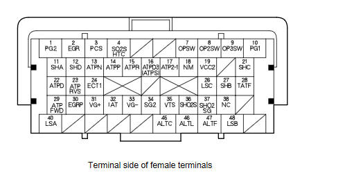
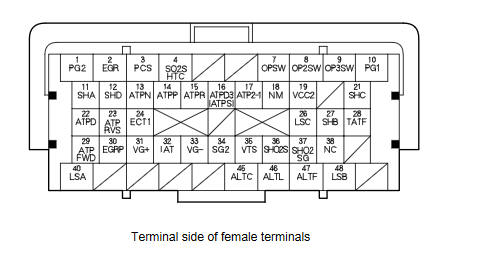
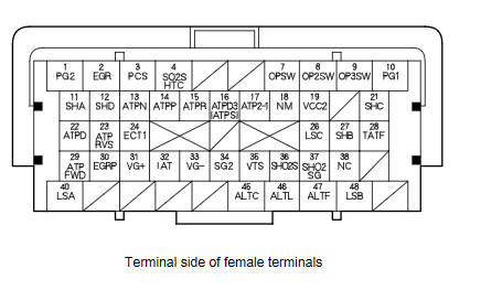
ECM/PCM Inputs and Outputs at ECM/PCM Connector B (49P)
|
Terminal number |
Wire color |
Terminal name |
Description |
Signal |
|
1 |
BRN*6 |
PG2 (POWER GROUND) |
Ground circuit for ECM/PCM circuit |
Less than 0.2 V at all times |
|
2 |
BLU/RED*6 |
EGR (EXHAUST GAS RECIRCULATION (EGR) VALVE) |
Drives EGR valve |
With EGR operating: duty controlled With EGR not operating: about 0 V |
|
3 |
YEL/BLU*6 |
PCS (EVAPORATIVE EMISSION (EVAP) CANISTER PURGE VALVE) |
Drives EVAP canister purge valve |
With engine running, engine coolant below 140 В°F (60 В°C): battery voltage With engine running, engine coolant above 140 В°F (60 В°C): duty controlled |
|
4 |
BLK/WHT*6 |
SO2SHTC (SECONDARY HEATED OXYGEN SENSOR (SECONDARY HO2S) HEATER (SENSOR 2)) |
Drives secondary HO2S heater (sensor 2) |
With ignition switch ON (II): battery voltage With warmed up engine running: duty controlled |
|
7 |
YEL/RED*6 |
OPSW (OIL PRESSURE SWITCH) |
Detects engine oil pressure signal |
With ignition switch in LOCK (0): about 0 V With engine running: battery voltage |
|
8*1 |
BLU/RED*6 |
OP2SW (TRANSMISSION FLUID PRESSURE SWITCH A (2ND CLUTCH)) |
Detects transmission fluid pressure switch A (2nd clutch) input signal |
With ignition switch ON (II):
|
|
9*1 |
BLU/WHT*6 |
OP3SW (TRANSMISSION FLUID PRESSURE SWITCH B (3RD CLUTCH)) |
Detects transmission fluid pressure switch B (3rd clutch) input signal |
With ignition switch ON (II):
|
|
10 |
BLK |
PG1 (POWER GROUND) |
Ground circuit for ECM/PCM circuit |
Less than 0.2 V at all times |
|
11*1 |
BLU/BLK*6 |
SHA (SHIFT SOLENOID VALVE A) |
Drives shift solenoid valve A |
With engine running in D (in 2nd and 4th gears), S (in 2nd and 4th gears), D3 (in 2nd gear), and 2: battery voltage With engine running in P, R, N, 1, D (in 1st, 3rd, and 5th gears), S (in 1st, 3rd, and 5th gears), and D3 (in 1st and 3rd gears): about 0 V |
|
12*1 |
GRN/RED*6 |
SHD (SHIFT SOLENOID VALVE D) |
Drives shift solenoid valve D |
With engine running in P and R: battery voltage With engine running in N: about 0 V |
|
13*1 |
RED/BLK*6 |
ATPN (TRANSMISSION RANGE SWITCH IN N) |
Detects transmission range switch N position input signal |
With ignition switch ON (ll) in N: about 0 V With ignition switch ON (ll) in any position other than N: battery voltage |
|
14*1 |
BLU/BLK*6 |
ATPP (TRANSMISSION RANGE SWITCH IN P) |
Detects transmission range switch P position input signal |
With ignition switch ON (ll) in P: about 0 V With ignition switch ON (ll) in any position other than P: battery voltage |
|
15*1 |
WHT*6 |
ATPR (TRANSMISSION RANGE SWITCH IN R) |
Detects transmission range switch R position input signal |
With ignition switch ON (ll) in R: about 0 V With ignition switch ON (ll) in any position other than R: battery voltage |
|
*1: |
A/T |
|
*6: |
9-10 models and 11-13 models (M/T) |
|
*7: |
11-13 models (A/T) |
ECM/PCM Inputs and Outputs at ECM/PCM Connector B (49P)
|
Terminal number |
Wire color |
Terminal name |
Description |
Signal |
|
16*5 |
RED*6 |
ATPD3 (TRANSMISSION RANGE SWITCH IN D3) |
Detects transmission range switch D3 position input signal |
With ignition switch ON (ll) in D3: about 0 V With ignition switch ON (ll) in any position other than D3: battery voltage |
|
16*4 |
RED*6 |
ATPS (TRANSMISSION RANGE SWITCH IN S) |
Detects transmission range switch S position input signal |
With ignition switch ON (ll) in S: about 0 V With ignition switch ON (ll) in any position other than S: battery voltage |
|
17*5 |
BLU |
ATP2-1 (TRANSMISSION RANGE SWITCH 2-1) |
Detects transmission range switch 2 and 1 position input signal |
With ignition switch ON (ll) in 2 and 1: about 0 V With ignition switch ON (ll) in any position other than 2 and 1: battery voltage |
|
18*1 |
WHT/RED*6 |
NM (INPUT SHAFT (MAINSHAFT) SPEED SENSOR) |
Detects input shaft (mainshaft) speed sensor signal |
With ignition switch ON (II): about 0 V or about 5.0 V With engine running in N: pulses |
|
19 |
YEL/BLU*6 |
VCC2 (SENSOR VOLTAGE) |
Provides sensor voltage |
With ignition switch ON (II): about 5.0 V |
|
21*1 |
GRN*6 |
SHC (SHIFT SOLENOID VALVE C) |
Drives shift solenoid valve C |
With engine running in R, D (in 3rd and 4th gears), S (in 3rd and 4th gears), and D3 (in 3rd gear): battery voltage With engine running in P, N, 2, 1, D (in 1st, 2nd, and 5th gears), S (in 1st, 2nd, and 5th gears), and D3 (in 1st and 2nd gears): about 0 V |
|
22*1 |
PNK |
ATPD (TRANSMISSION RANGE SWITCH IN D) |
Detects transmission range switch D position input signal |
With ignition switch ON (ll) in D: about 0 V With ignition switch ON (ll) in any position other than D: battery voltage |
|
23*1 |
YEL |
ATPRVS (TRANSMISSION RANGE SWITCH IN RVS) |
Detects transmission range switch R position input signal |
With ignition switch ON (ll) in R: about 0 V With ignition switch ON (ll) in any position other than R: battery voltage |
|
24 |
RED/WHT*6 |
ECT1 (ENGINE COOLANT TEMPERATURE (ECT) SENSOR 1) |
Detects ECT sensor 1 signal |
With ignition switch ON (II): about 0.1пјЌ4.8 V (depending on engine coolant temperature) |
|
26*1 |
BLU/YEL*6 |
LSC (A/T CLUTCH PRESSURE CONTROL SOLENOID VALVE C) |
Drives A/T clutch pressure control solenoid valve C |
With ignition switch ON (II): duty controlled |
|
27*1 |
GRN/WHT*6 |
SHB (SHIFT SOLENOID VALVE B) |
Drives shift solenoid valve B |
With engine running in R, 1, D (in 1st, 4th, and 5th gears), S
(in 1st, 4th, and 5th gears), and D3 (in 1st gear): battery voltage |
|
28*1 |
RED/YEL*6 |
TATF (ATF TEMPERATURE SENSOR) |
Detects ATF temperature signal |
With ignition switch ON (II): about 0.2пјЌ4.0 V (depending on ATF temperature) |
|
*1: |
A/T |
|
*4: |
A/T (with paddle shifter) |
|
*5: |
A/T (without paddle shifter) |
|
*6: |
09-10 models and 11-13 models (M/T) |
|
*7: |
11-13 models (A/T) |
ECM/PCM Inputs and Outputs at ECM/PCM Connector B (49P)
|
Terminal number |
Wire color |
Terminal name |
Description |
Signal |
|
29*1 |
BLU/YEL*6 |
ATPFWD (TRANSMISSION RANGE SWITCH IN FWD) |
Detects transmission range switch D, D3, 2, and S position input signals |
With ignition switch ON (ll) in D, D3, 2, and S: about 0 V With ignition switch ON (ll) in any position other than D, D3, 2, and S: battery voltage |
|
30 |
WHT/BLK*6 |
EGRP (EXHAUST GAS RECIRCULATION (EGR) VALVE POSITION SENSOR) |
Detects EGR valve position sensor signal |
With engine running: about 1.2пјЌ3.5 V (depending on EGR valve) |
|
31 |
RED/GRN*6 |
VGпј‹ (MASS AIR FLOW (MAF) SENSOR пј‹SIDE) |
Detects MAF sensor signal |
At idle with warmed up engine and no electrical load: about 1.7 V |
|
32 |
RED/YEL*6 |
IAT (INTAKE AIR TEMPERATURE (IAT) SENSOR) |
Detects IAT sensor signal |
With ignition switch ON (II): about 0.1пјЌ4.0 V |
|
33 |
BLK/RED*6 |
VGпјЌ (MASS AIR FLOW (MAF) SENSOR пјЌSIDE) |
Ground for MAF sensor signal |
Less than 0.2 V at all times |
|
34 |
GRN/YEL*6 |
SG2 (SENSOR GROUND) |
Sensor ground |
Less than 0.2 V at all times |
|
35 |
GRN/YEL*6 |
VTS (ROCKER ARM OIL CONTROL SOLENOID) |
Drives rocker arm oil control solenoid |
At idle: about 0 V |
|
36 |
WHT/RED*9 |
SHO2S (SECONDARY HEATED OXYGEN SENSOR (SECONDARY HO2S) SENSOR 2) |
Detects secondary HO2S (sensor 2) signal |
With throttle fully opened at idle, and warmed up engine: above 0.6 V With throttle quickly closed: below 0.4 V |
|
37*8 |
BLU |
SHO2SG (SECONDARY HEATED OXYGEN SENSOR (SECONDARY HO2S) SENSOR 2 GROUND) |
Ground for secondary HO2S (sensor 2) |
Less than 0.2 V at all times |
|
38 |
BLK/WHT*6 |
NC (OUTPUT SHAFT (COUNTERSHAFT) SPEED SENSOR) |
Detects output shaft (countershaft) speed sensor signal |
With ignition switch ON (II): about 0 V or about 5.0 V Driving: pulses |
|
40*1 |
RED/BLK*6 |
LSA (A/T CLUTCH PRESSURE CONTROL SOLENOID VALVE A) |
Drives A/T clutch pressure control solenoid valve A |
With ignition switch ON (II): duty controlled |
|
45 |
WHT/GRN*6 |
ALTC (ALTERNATOR CONTROL) |
Sends alternator control signal |
With warmed up engine running: about 5.0 V(depending on electrical load) |
|
46 |
WHT/BLU*6 |
ALTL (ALTERNATOR L SIGNAL) |
Detects alternator L signal |
With ignition switch ON (II): about 0 V With engine running: battery voltage |
|
47 |
WHT/RED*6 |
ALTF (ALTERNATOR FR SIGNAL) |
Detects alternator FR signal |
With engine running: about 2.6пјЌ3.7 V (depending on electrical load) |
|
48*1 |
BRN/WHT*6 |
LSB (A/T CLUTCH PRESSURE CONTROL SOLENOID VALVE B) |
Drives A/T clutch pressure control solenoid valve B |
With ignition switch ON (II): duty controlled |
|
*1: |
A/T |
|
*6: |
09-10 models and 11-13 models (M/T) |
|
*7: |
11-13 models (A/T) |
|
*8: |
11-13 models |
|
*9: |
09-10 models |
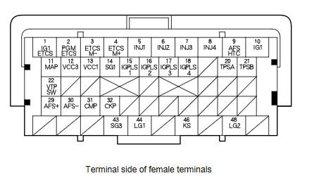
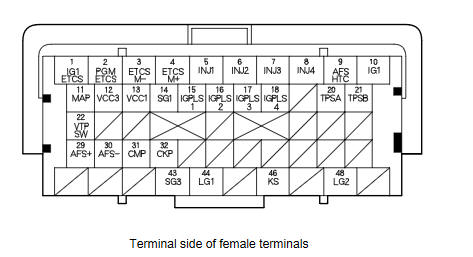
ECM/PCM Inputs and Outputs at ECM/PCM Connector C (49P)
|
Terminal number |
Wire color |
Terminal name |
Description |
Signal |
|
1 |
WHT*6 |
IG1ETCS (IGNITION SIGNAL ETCS) |
Detects ignition signal |
With ignition switch ON (II): battery voltage |
|
2 |
BRN*6 |
PGMETCS (POWER GROUND ETCS) |
Ground circuit for ECM/PCM circuit |
Less than 0.2 V at all times |
|
3 |
YEL |
ETCSMпјЌ (THROTTLE ACTUATOR пјЌSIDE) |
Ground for throttle actuator |
With ignition switch ON (II) and accelerator pedal released: about 0 V With ignition switch ON (II) and accelerator pedal pressed: about 1.8 V |
|
4 |
YEL/RED*6 |
ETCSMпј‹ (THROTTLE ACTUATOR пј‹SIDE) |
Drives throttle actuator |
About 1.5 V immediately after turning ignition switch ON (II), then about 0 V |
|
5 |
BRN*6 |
INJ1 (No. 1 INJECTOR) |
Drives No. 1 injector |
At idle: duty controlled With ignition switch ON (II): battery voltage |
|
6 |
RED*6 |
INJ2 (No. 2 INJECTOR) |
Drives No. 2 injector |
|
|
7 |
BLU |
INJ3 (No. 3 INJECTOR) |
Drives No. 3 injector |
|
|
8 |
YEL*6 |
INJ4 (No. 4 INJECTOR) |
Drives No. 4 injector |
|
|
9 |
GRN |
AFSHTC (AIR FUEL RATIO (A/F) SENSOR HEATER CONTROL (SENSOR 1)) |
Drives A/F sensor heater (sensor 1) |
With ignition switch ON (II): battery voltage With warmed up engine running: duty controlled |
|
10 |
BLK/RED*6 |
IG1 (IGNITION SIGNAL) |
Detects ignition signal |
With ignition switch ON (II): battery voltage |
|
11 |
GRN/RED*6 |
MAP (MANIFOLD ABSOLUTE PRESSURE (MAP) SENSOR) |
Detects MAP sensor signal |
With ignition switch ON (II): about 3.0 V At idle: about 1.0 V (depending on engine speed) |
|
12 |
BLU*6 |
VCC3 (SENSOR VOLTAGE) |
Provides sensor reference voltage |
With ignition switch ON (II): about 5.0 V |
|
13 |
YEL/RED*6 |
VCC1 (SENSOR VOLTAGE) |
Provides sensor reference voltage |
With ignition switch ON (II): about 5.0 V |
|
14 |
GRN/WHT*6 |
SG1 (SENSOR GROUND) |
Sensor ground |
Less than 0.2 V at all times |
|
15 |
WHT |
IGPLS1 (No. 1 IGNITION COIL PULSE) |
Drives No. 1 ignition coil |
With ignition switch ON (II): about 0 V With engine running: pulses |
|
16 |
WHT/GRN*6 |
IGPLS2 (No. 2 IGNITION COIL PULSE) |
Drives No. 2 ignition coil |
|
|
17 |
WHT/BLK*6 |
IGPLS3 (No. 3 IGNITION COIL PULSE) |
Drives No. 3 ignition coil |
|
|
18 |
WHT/BLU*6 |
IGPLS4 (No. 4 IGNITION COIL PULSE) |
Drives No. 4 ignition coil |
|
*6: |
09-10 models and 11-13 models (M/T) |
|
*7: |
11-13 models (A/T) |
ECM/PCM Inputs and Outputs at ECM/PCM Connector C (49P)
|
Terminal number |
Wire color |
Terminal name |
Description |
Signal |
|
20 |
RED/BLK*6 |
TPSA (THROTTLE POSITION (TP) SENSOR A) |
Detects TP sensor A signal |
With ignition switch ON (II) and accelerator pedal released:
about 0.8 V |
|
21 |
RED |
TPSB (THROTTLE POSITION (TP) SENSOR B) |
Detects TP sensor B signal |
With ignition switch ON (II) and accelerator pedal released:
about 1.7 V |
|
22 |
BLU/BLK*6 |
VTPSW (ROCKER ARM OIL PRESSURE SWITCH) |
Detects rocker arm oil pressure switch signal |
At idle: about 0 V |
|
29 |
RED*6 |
AFSпј‹ (AIR FUEL RATIO (A/F) SENSOR (SENSOR 1) пј‹SIDE) |
Detects A/F sensor (sensor 1) signal |
At idle: about 2.2 V |
|
30 |
RED/YEL*6 |
AFSпјЌ (AIR FUEL RATIO (A/F) SENSOR (SENSOR 1) пјЌSIDE) |
Detects A/F sensor (sensor 1) signal |
At idle: about 1.8 V |
|
31 |
GRN |
CMP (CAMSHAFT POSITION (CMP) SENSOR) |
Detects CMP sensor signal |
With engine running: pulses |
|
32 |
BLU |
CKP (CRANKSHAFT POSITION (CKP) SENSOR) |
Detects CKP sensor signal |
With engine running: pulses |
|
43 |
GRN*6 |
SG3 (SENSOR GROUND) |
Sensor ground |
Less than 0.2 V at all times |
|
44 |
BRN/YEL*6 |
LG1 (LOGIC GROUND) |
Ground circuit for ECM/PCM circuit |
Less than 0.2 V at all times |
|
46 |
RED/BLU*9 |
KS (KNOCK SENSOR) |
Detects knock sensor signal |
With engine knocking: pulses |
|
48 |
BRN/YEL*6 |
LG2 (LOGIC GROUND) |
Ground circuit for ECM/PCM circuit |
Less than 0.2 V at all times |
|
*6: |
09-10 models and 11-13 models (M/T) |
|
*7: |
11-13 models (A/T) |
|
*8: |
11-13 models |
|
*9: |
09-10 models |
ECM/PCM Electrical Connections
ECM/PCM Electrical Connections (cont'd)
ECM/PCM Electrical Connections (cont'd)
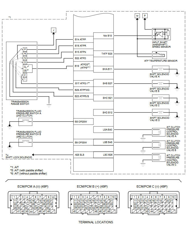
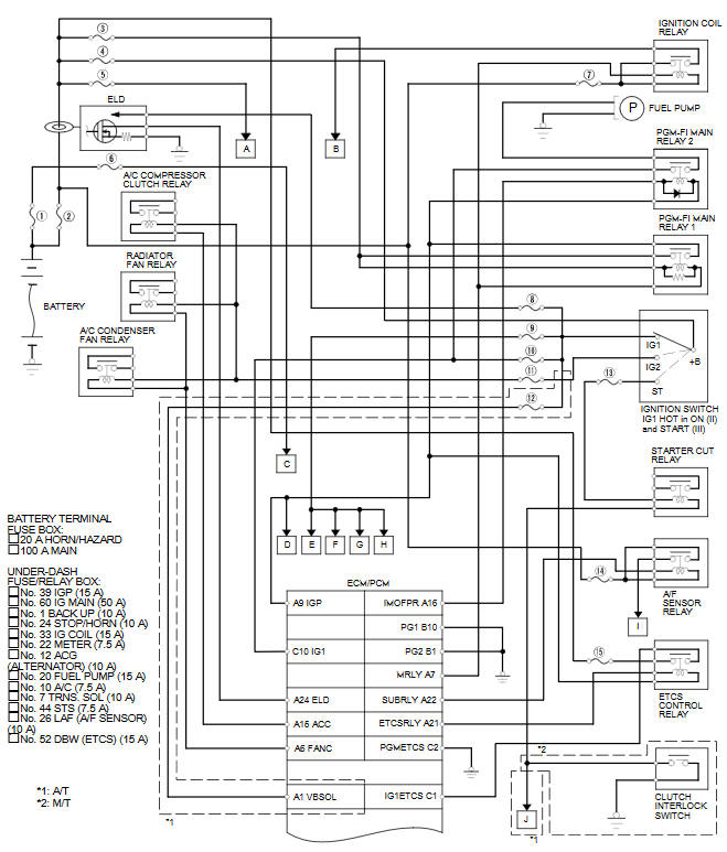
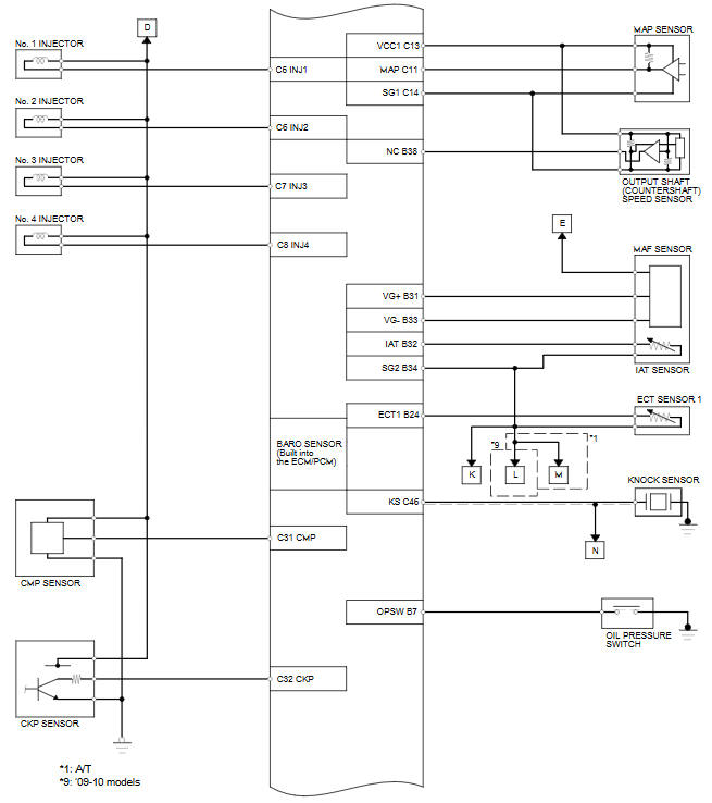
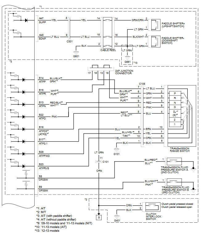
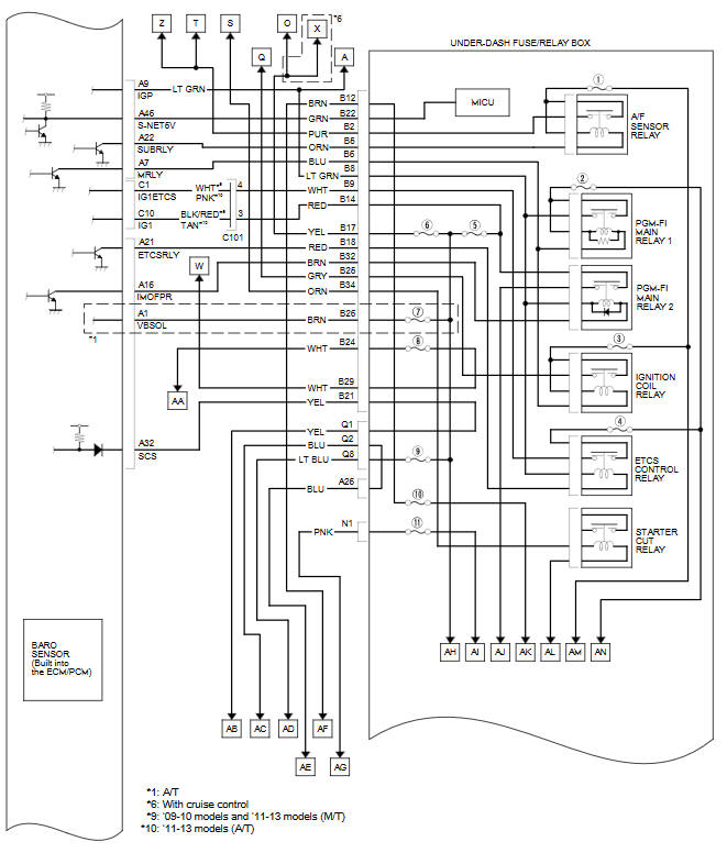
ECM/PCM Circuit Diagram

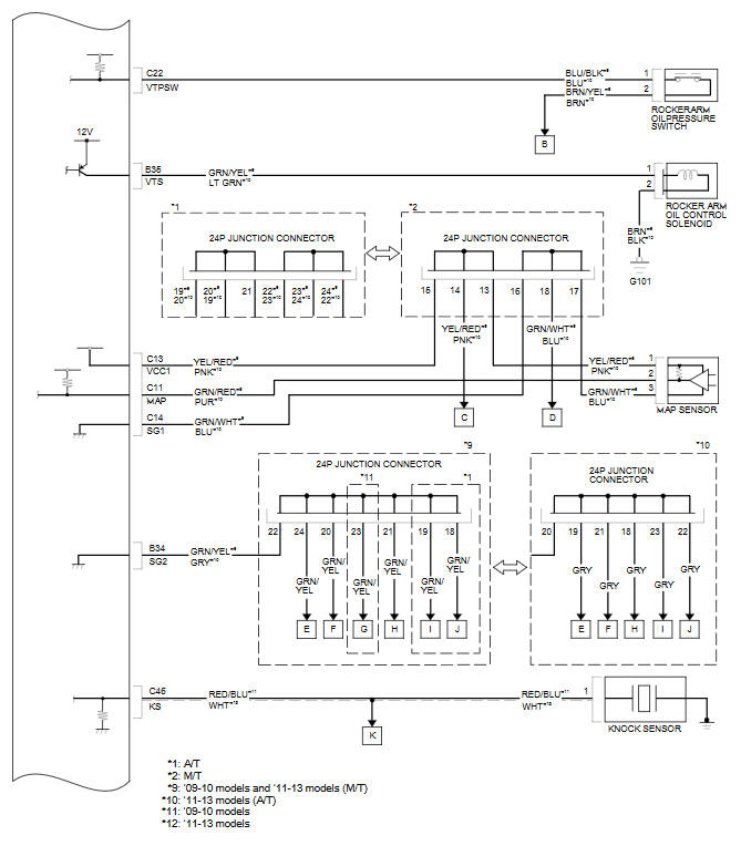
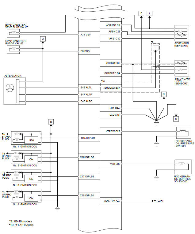
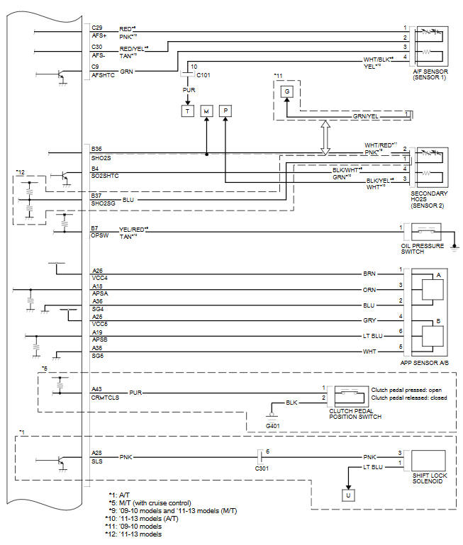
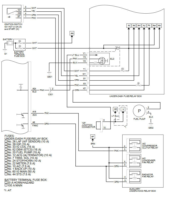
ECM/PCM Circuit Diagram (cont'd)
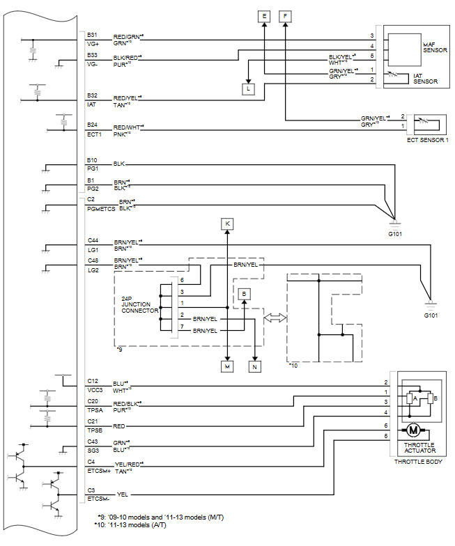

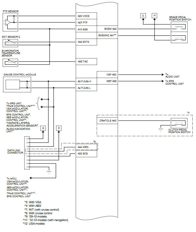
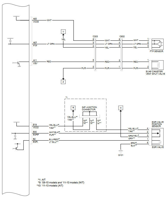
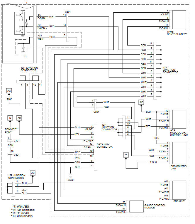
ECM/PCM Circuit Diagram (cont'd)
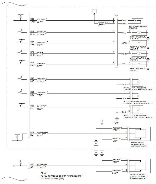
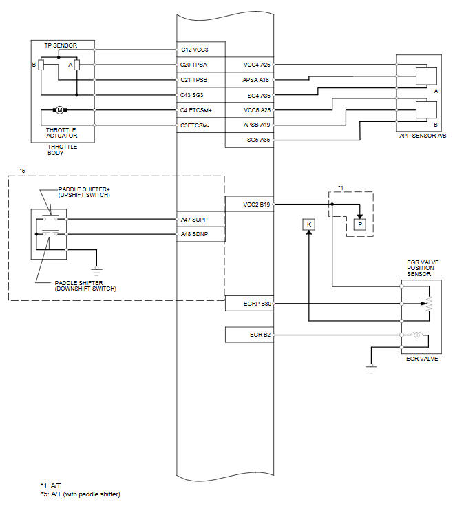
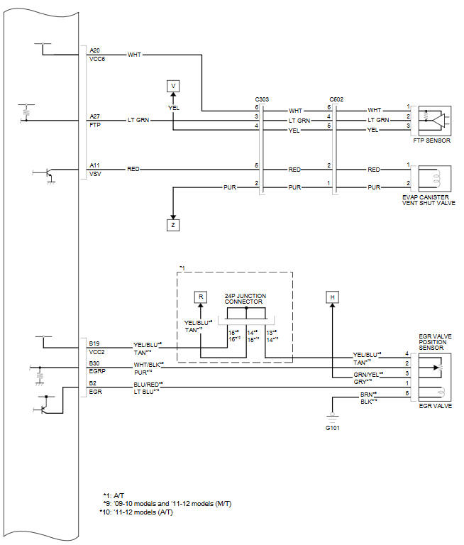
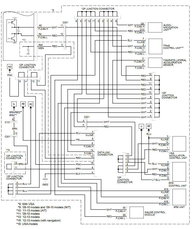
ECM/PCM Circuit Diagram (cont'd)
ECM/PCM Circuit Diagram (cont'd)
ECM/PCM Circuit Diagram (cont'd)
ECM/PCM Circuit Diagram (cont'd)
See also:
Exploded View
@font-face{font-family:
"Honda_SymbolMarkeng";src:url(/statics/ho_prod_2/txt/Honda_SymbolMark_enu3.txt);}@font-face{font-family:
"Honda_Special_Symbols";src:url(/sta ...
Shifter Input and Linkage
Paddle Shifter (Downshift Switch) Replacement (A/T)
SRS components are located in this area. Review the SRS component locations
and the precautions and procedures before doi ...
Engine Number
@font-face{font-family:
"Honda_SymbolMarkeng";src:url(/statics/ho_prod_2/txt/Honda_SymbolMark_enu3.txt);}@font-face{font-family:
"Honda_Sp ...
Categories
